
Methods for purification of phenol

a technology of phenol and purification method, which is applied in the field of purification and recovery of phenol, can solve the problems of contaminating the final phenol product, and affecting the quality of the phenol product for many end-use applications

Inactive Publication Date: 2005-06-23
SABIC INNOVATIVE PLASTICS IP BV
View PDF11 Cites 13 Cited by
  • Summary
  • Abstract
  • Description
  • Claims
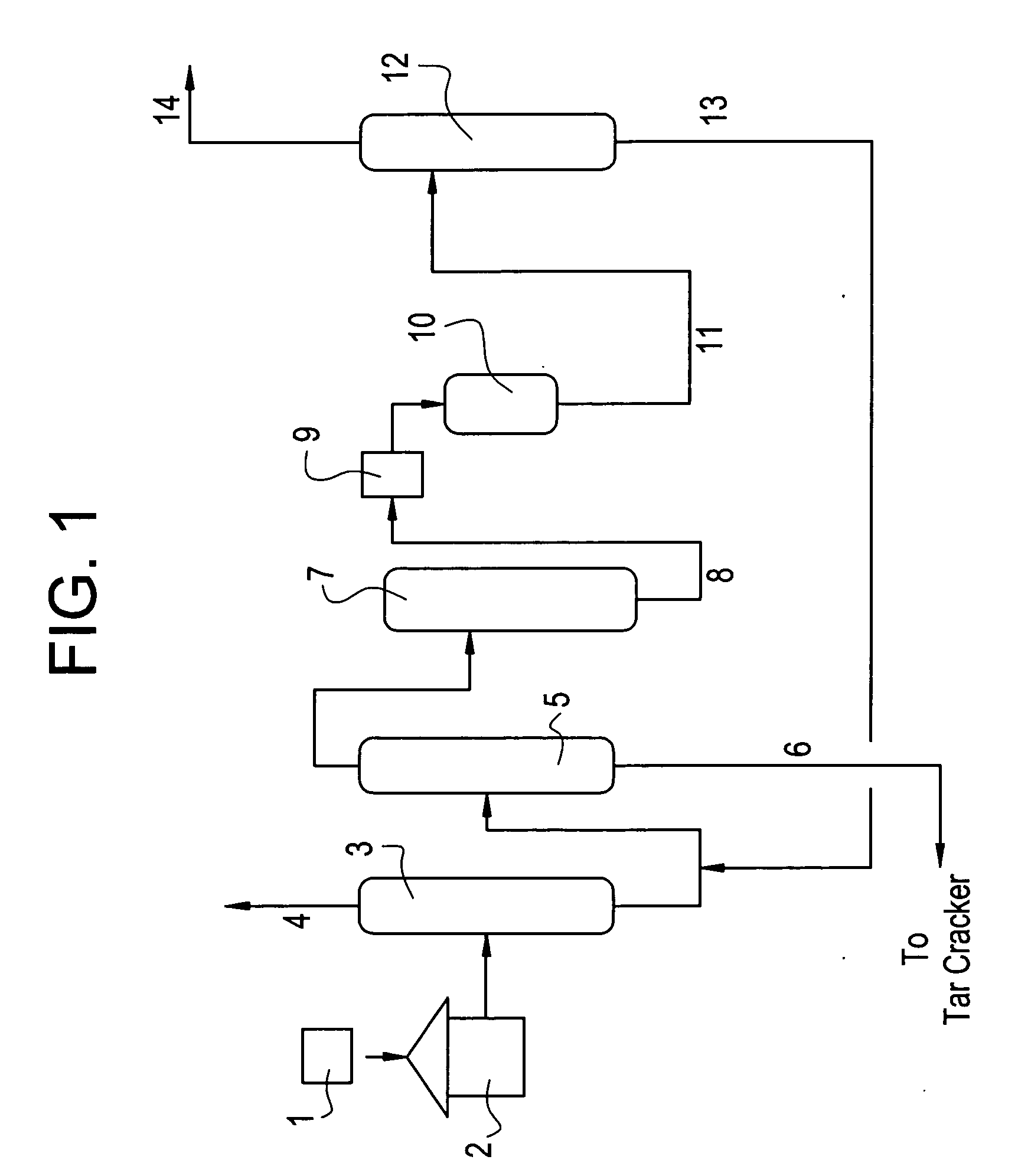
  • Application Information

AI Technical Summary

Benefits of technology

[0007] A one-step process for producing a purified phenol stream comprises contacting a phenol stream containing an initial concentration of hydroxyacetone and methylbenzofuran with an acidic ion exchange resin at a temperature of 50° C. to 100° C. to concurrently reduce the initial concentration of the hydroxyacetone and the methylbenzofuran in the phenol stream to produce the purified phenol stream.
[0008] In another embodiment, a continuous process for producing a purified phenol stream comprises contacting a phenol stream at a temperature of 50° C. to 100° C. at a weighted hourly space velocity of 0.1 to 5 with a sulfonated styrene-divinylbenzene acidic ion exchange resin, wherein the resin is crosslinked with greater than or equal to about 8 weight percent of divinylbenzene relative to an overall weight of said acidic ion exchange resin, and wherein the phenol stream has an initial concentration of hydroxyacetone and methylbenzofuran to concurrently reduce the initial concentration of the hydroxyacetone and methylbenzofuran and form products having a boiling point greater than phenol; and distilling said treated phenol stream.
[0009] In yet another embodiment, a process comprises contacting a phenol stream containing an initial concentration of hydroxyacetone and methylbenzofuran with an acidic ion exchange resin at a temperature of about 50° C. to about 100° C. to concurrently reduce the initial concentration of the hydroxyacetone and the methylbenzofuran in the phenol stream.
[0010] The present disclosure may be understood more readily by reference to the following detailed description of the various features of the disclosure, the figure, and the examples included therein.

Problems solved by technology

For example, the presence of acetol and methylbenzofuran impurities in phenol renders the phenol product quality unacceptable for many end-use applications, such as in the production of bisphenol-A, diphenyl carbonate, and polycarbonate.
Furthermore, phenol containing acetol and methylbenzofuran impurities tends to discolor upon aging, or during subsequent reactions, such as during sulfonation and chlorination reactions.
Acetol is particularly difficult to remove from phenol in the downstream process since it co-distills with phenol during rectification processes, thereby contaminating the final phenol product.
Also, acetol is known to condense with phenol under the operating conditions to form methylbenzofuran(s), thereby leading to elevated equilibrium concentrations of MBF, which is / are very difficult to separate from phenol by distillation methods due to formation of an azeotrope with the phenol.
Such additional steps increase operational costs, which are not desirable for a high volume product like phenol.

Method used


Image

  • Methods for purification of phenol

Examples


example 1

[0022] In this example, a continuous process for reduction of HA and MBF from a synthetic mixture comprising phenol, HA, and MBF is described.

[0023] In a continuous reactor system, a synthetic mixture of phenol, HA (209 parts per million) and MBF (9 parts per million) was passed through a Bayer K2431 ion exchange resin (5 grams; 15% cross link by divinyl benzene obtained Bayer Co.) at 90° C. at a weighted hourly space velocity (WHSV) of 1.66 and a residence time of 0.6 hours. The amount of HA and MBF in the resulting treated phenol effluent was found to be less than 6 parts per million and less than 1 parts per million, respectively, as measured by gas chromatography (GC).

examples 2-5

[0024] These examples describe a continuous process for concurrent reduction of acetol and methylbenzofuran from the synthetic mixture comprising phenol, HA, and MBF as described in Example 1. The synthetic mixture comprising phenol, HA and MBF was passed through a Bayer K2431 (15% cross link by divinyl benzene obtained Bayer Co.) ion exchange resin (5 grams). The parts per million of HA and MBF before and after treatment with the ion exchange resin are included the Table I below.

TABLE IEffect of Temperature and WHSV on the reduction of HA and MBF fromphenolCatalyst BedExampleTemperatureHA (ppm)MBF (ppm)No.° C.WHSVBeforeAfterBeforeAfter290° C.1.02096522390° C.2.22096526490° C.3.22096526570° C.1.023463425

example 6

[0025] This example provides a continuous process for reduction of HA and MBF from an actual phenol plant feed.

[0026] In a continuous reactor system, the actual phenol plant feed containing phenol, HA (215.7 parts per million), MBF (22.33 parts per million), and other carbonyl impurities was passed through a Bayer K2431 (15% cross link by divinyl benzene obtained Bayer Co.) ion exchange resin (12.5 grams) at 70° C. for a period of 57 days. Data for the first 17 days is included in the Table II below.

TABLE IIEffect of time on the removal of HA and MBF from phenolstreamTime(hours)WHSVHA (ppm)MBF (ppm)Initial1.60215.722.33541.570.87617.81711.560.87615.67771.580.87616.24941.540.87616.521011.640.87616.741661.610.87621.021741.560.87621.801901.610.87620.141981.570.87620.372141.570.87622.382221.590.87621.623581.540.87627.723671.540.87626.883821.610.87626.943901.560.87626.854061.600.87626.424151.610.87628.39

[0027] It is observed that generally after about 166 minutes or greater, the MBF c...


PUM

PropertyMeasurementUnit
temperatureaaaaaaaaaa

Abstract

A process for producing a purified phenol stream generally includes contacting a phenol stream containing an initial concentration of hydroxyacetone and methylbenzofuran with an acidic ion exchange resin at a temperature of 50° C. to 100° C. to concurrently reduce the initial concentration of the hydroxyacetone and the methylbenzofuran in the phenol stream to produce the purified phenol stream.

Description

CROSS-REFERENCE TO RELATED APPLICATIONS [0001] This application claims priority to U.S. Provisional Application Ser. No. 60 / 530,563, filed Dec. 18, 2003.BACKGROUND [0002] The present disclosure generally relates to a method for the purification and recovery of phenol. [0003] A three-step cumene process generally produces about 95 percent of the phenol used in the world. Starting from benzene, the three-step cumene process involves (1) alkylation of benzene with propene to form cumene, which is typically catalyzed by phosphoric acid or aluminum chloride; (2) oxidation of cumene to cumene hydroperoxide (also referred to as “CHP”) using molecular oxygen; and (3) cleavage of CHP to phenol and acetone, which is typically catalyzed by sulfuric acid. In addition to the phenol and acetone products, unreacted cumene and various other by-products, including alpha-methylstyrene, acetophenone, cumylphenol, dimethylbenzyl alcohol, methylbenzofuran (sometimes referred to as “MBF”), and traces of ...

Claims


Application Information

Patent Timeline
Patent Type & Authority Applications(United States)
IPC IPC(8): C07C37/82C07C37/86
CPCC07C37/82C07C39/04C07C37/86
Inventor TATAKE, PRASHANT ANILHASYAGAR, UMESH KRISHNAKUMBHAR, PRAMOND SHANKARSINGH, BHARATFULMER, JOHN WILLIAM
Owner SABIC INNOVATIVE PLASTICS IP BV
Learn More