
Surface modification of castings

Inactive Publication Date: 2005-09-22
NAT RES COUNCIL OF CANADA
View PDF3 Cites 22 Cited by
  • Summary
  • Abstract
  • Description
  • Claims
  • Application Information

AI Technical Summary

Benefits of technology

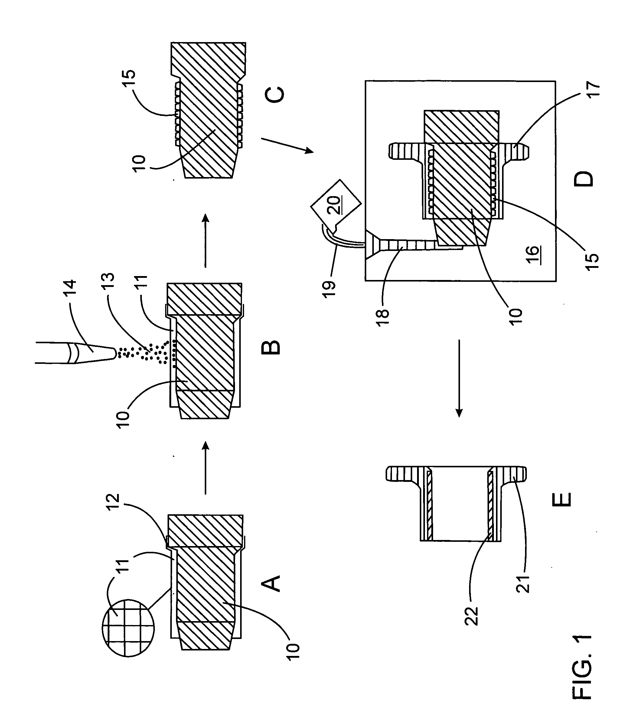
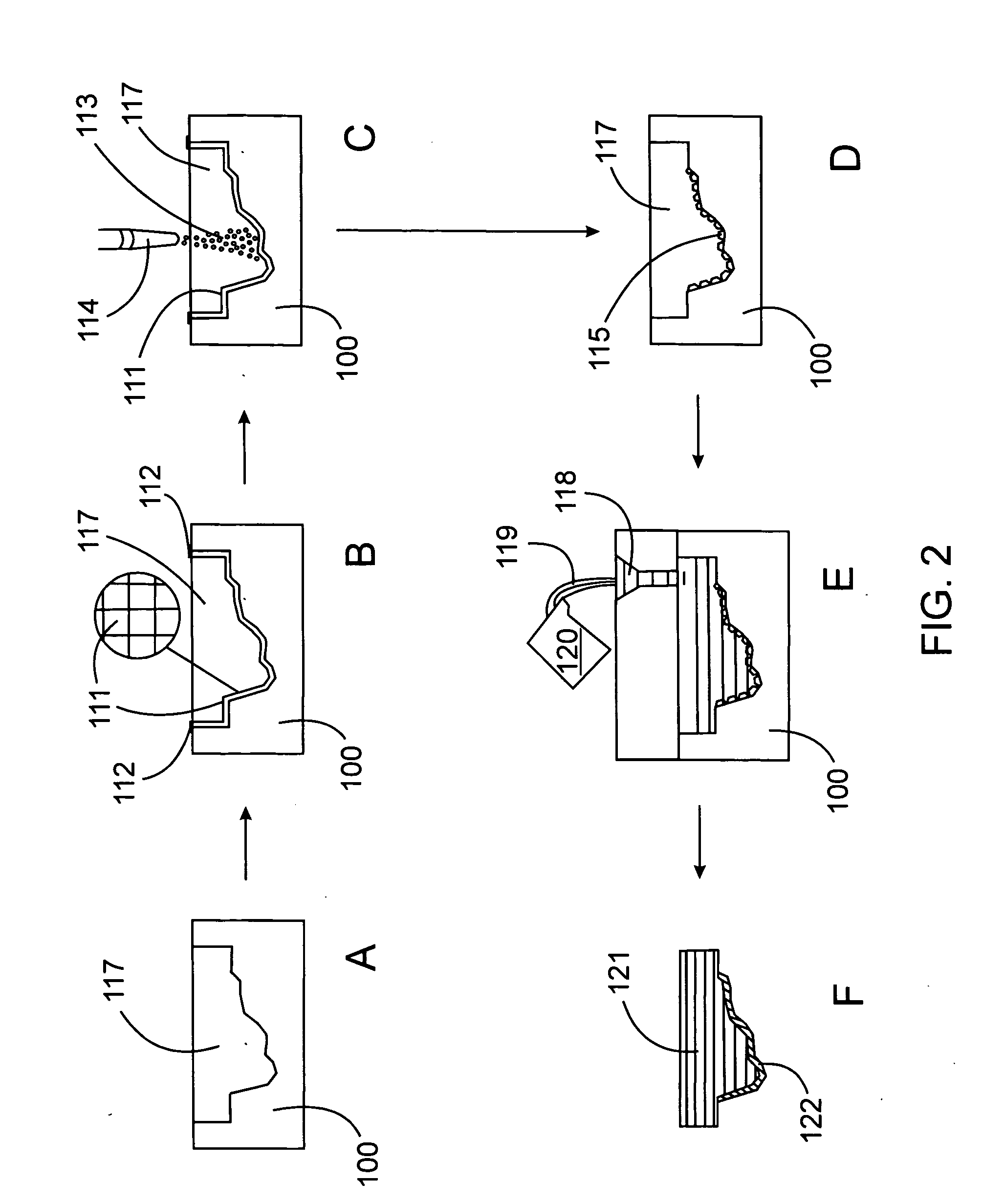
[0016] The present invention may provide any one of or any combination of a number of surprising advantages. Spalling from the casting mould surface is reduced leading to more uniform layers. Coating layers on the mould may be formed which are thicker than those formed using conventional methods. Higher quality and thicker surface layers may be formed on casting surfaces. Castings may be formed with specially formed surfaces having fewer or no defects or inclusions, which significantly improves wear resistance, corrosion resistance, heat resistance or combinations thereof. Castings have improved metallurgical properties and surface quality.
[0017] Furthermore, there is very little restriction on the shape and size of the casting. Internal surfaces of castings can be strengthened by applying coatings to casting cores. Surface modifications to castings are applied during the casting process so that net or near-net shaped castings can be produced.
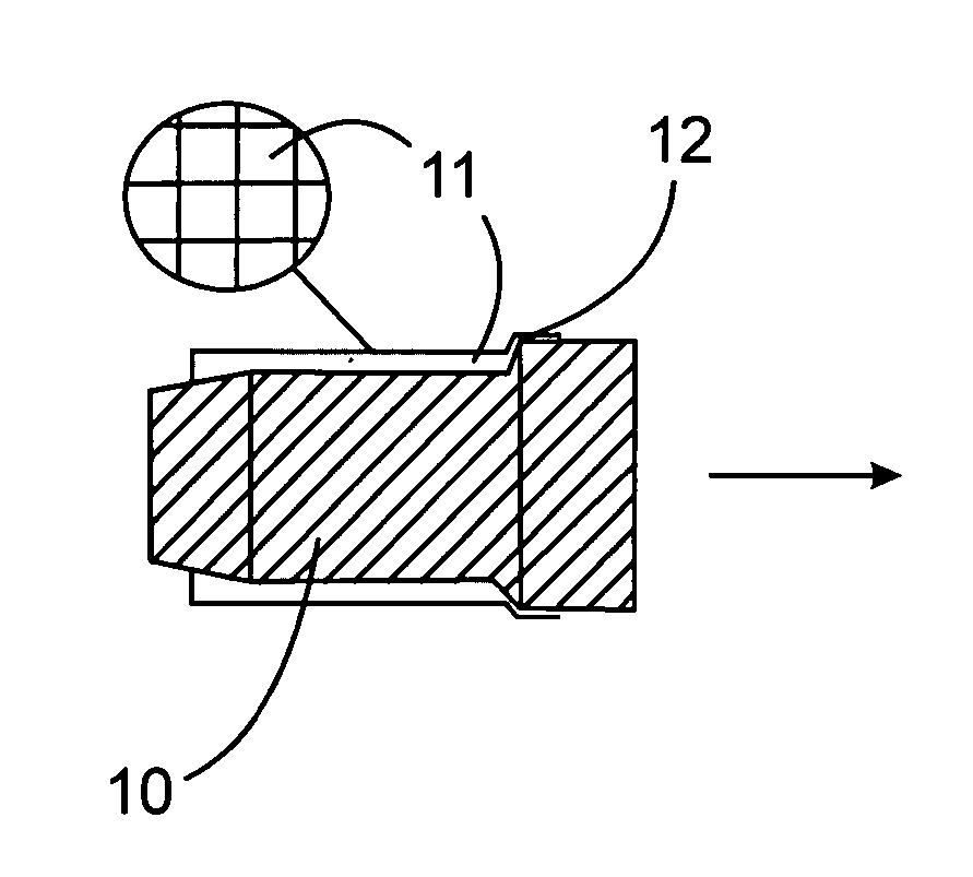
[0023] Perforations may be arranged randomly or in a regular pattern on the mask. Any shape, size and arrangement of the perforations on the mask may be used. In a preferred embodiment, the perforations are arranged such that a maximum opening ratio is obtained. The opening ratio is the ratio between the area of the perforation openings and the total area of the mask. A maximum opening ratio permits maximization of surface coverage of the casting mould by the coating material and reduces the chance of plugging the mask. Masks with a regular pattern of perforations are preferred, more preferably perforations are arranged in a regular grid pattern. Meshes are preferred.
[0028] Without being held to any particular mode of action, it is thought that the use of a perforated mask divides the spray-coating into smaller fragments for an initial coating. It is thought that internal stresses caused by shrinking of the coating layer are directly related to lateral dimensions of the coating layer and that the use of a perforated mask to form coating fragments significantly reduces the internal stresses and the tendency of the coating layer to spall from the casting mould surface. Reduction in the tendency of the coating layer to spall from the casting mould is thought to permit application of thicker coating layers to the mould surface, which results in thicker surface layers on the casting.
[0033] The perforated mask may be removed from the casting mould after spray-coating is complete, or, in some circumstances the mask may be left with the mould to ultimately form part of the surface layer on the casting. The mask may be left with the mould when the mask material and the casting material are compatible and / or inclusion of the mask material in the casting process causes no detrimental effects or even improves the properties of the casting. For example, if the mask is made of stainless steel and the casting material is an iron-based alloy, the mask may be incorporated into the casting and may even provide some alloying strengthening to the casting. The incorporated mask may also provide extra composite strengthening if the mask is significantly stronger than the casting material, such as in the case of a steel mask in an aluminum casting.
[0034] After depositing a certain required or desired thickness of the coating material at a specified area of the casting mould using the perforated mask, a thin overlay of coating material can be further applied to the entire mould without the use of the mask, resulting in a coating layer having continuous coverage on the casting mould surface and convoluted morphology with low stress concentration. Such a structure further permits the formation of a thicker and more uniform coating layer. Minimum thickness of the overlay coating is determined by application requirements, while maximum thickness is controlled by stresses developed in the coating layer. Compared with conventional methods of applying a spray coating on a casting mould surface, the convoluted morphology of the coating layer helps relieve stresses in the coating layer, therefore, a thicker overlay coating may be applied in the present invention as compared to conventional methods.

Problems solved by technology

The requirements for material properties to combat each of these modes are different and often conflicting.
In many cases, a monolithic bulk material can only provide a good compromise to satisfy the differing and conflicting requirements.
However, using currently available casting surface modification techniques, the surface strengthening layers are prone to defects and it is difficult to achieve accurate dimensions and smooth surface finishes.
Additionally, in some applications, thick alloying layers cannot be easily applied.
One of the most apparent problems with methods involving the use of a binder is that high heat used during the casting process causes binder decomposition leading to defects in the casting, for example inclusions and gas porosities.
However, there are some limitations on each of the aforementioned methods.
For example, in method (2)(a) where perforated containers are used, it is very difficult to form a localized strengthening layer following the exact surface profile of a casting.
It is also very difficult to form thin strengthening layers.
Thus, different configurations of the (electro-) magnets are required for different casting designs, which is impractical and costly to apply for the production of frequently changing casting designs.
When the local profiles of the casting surface are complex, generating appropriate magnetic fields to hold the special material in the desired area and in uniform thickness becomes difficult.
Therefore, the formation of a uniform strengthening layer on the casting surface becomes very difficult, if not impossible.
It is also apparent that this method can only be applied to very simple, generally flat, casting surfaces on the bottom of the casting mould.
However, the major challenge for spray coating methods is to overcome the tendency for the coated layer to spall from the mould surface before casting.
In addition, spray coating has traditionally provided coatings of only a very limited thickness, likely as a result of the spallation problem.

Method used


Image

  • Surface modification of castings
  • Surface modification of castings
  • Surface modification of castings

Examples


example 1

[0051] A ceramic casting mould having a mould cavity was fabricated according to a process similar to the Unicast process (R. E. Greenwood, “Ceramic Moulding by the Unicast Process”, ASTME Tech. Paper No. CM67-534 (1967), the disclosure of which is herein incorporated by reference) and was fired at 950° C. for 4 hours to strengthen the mould. A perforated mask made of steel mesh (14 mesh with a wire diameter of 0.016 inch) was placed about 2 mm away from the mould cavity surface by clamping an extended portion of the mask to the mould surface surrounding the opening in the mould cavity. Using a Sulzer Metco™ type 5P-II Thermospray gun, a coating material consisting of Metco™ 15E (a self-fluxing nickel-based alloy powder having a composition of Ni: 70.5%, Cr: 17.0%, Fe: 4.0%, Si: 4.0%, B: 3.5%, C, 1.0% and a melting point of 1024° C.) was sprayed through the mask on to the mould cavity surface. To build up a thick coating layer, the spray was repeated 32 times without any sign of spa...

example 2

[0053] A coating layer on a vertical surface of a ceramic casting mould was produced in accordance with the procedure of Example 1 except that some areas of the mould surface were left unmasked. The coating layer was heated under reduced pressure (8×10⁻² Torr) to 1100° C., which is above the melting point of the Metco™ 15E, in 50 minutes and held for 2 hours. The coating layer was melted but still remained on the mould surface in the areas where the mask was used, as shown in FIG. 5. The coating thickness before heating to 1100° C. was 0.8 mm. However, in the areas where no mask was used, the coating layer completely spalled during the heating process, presumably due to high thermal stresses in the coating layer as a result of the large difference in thermal expansion coefficient between the coating layer and the ceramic casting mould.

example 3

[0054] A set of four ceramic casting moulds were fabricated using the process described in Example 1, the casting moulds having mould cavities for rectangular bar-shaped specimens 110 mm long by 30 mm wide with thicknesses of 8 mm, 16 mm, 24 mm and 32 mm, respectively. Steel mesh, as described in Example 1, was used to make masks corresponding to the cavities for each of the ceramic casting moulds. The masks were placed in each mould cavity about 2 mm from the mould cavity surface in each instance. Metco™ 15E nickel-based self-fluxing alloy was applied to each mould cavity surface by flame thermal spray coating under conditions described in Example 1. FIG. 6 shows the coating layer of the Metco™ 15E on the bottom 60 and side 61 surfaces of the mould cavity. P20 tool steel was melted and cast into the closed ceramic casting moulds at 1550° C. In each of the four cases, a continuous surface layer of the Metco™ 15E was alloyed to the surface of the steel casting. FIG. 7A shows one exam...


PUM

PropertyMeasurementUnit
Lengthaaaaaaaaaa
Lengthaaaaaaaaaa
Lengthaaaaaaaaaa

Abstract

A method of modifying a surface of a casting involves providing a casting mould; placing a perforated mask with the mould to define a masked area of the mould; spray-coating the masked area of the mould with a coating material selected for forming a surface layer on the casting; introducing a liquid casting material to the mould; and, solidifying the liquid casting material to form a surface modified casting. The present method reduces the tendency for the coating material to spall from the mould and permits the formation of thicker coating layers on the mould. Thicker and better quality surface layers may be formed on castings.

Description

FIELD OF THE INVENTION [0001] The present invention relates to methods of modifying surfaces of castings and to castings produced by casting processes. In particular, the present invention relates to spray-coating a casting mould and forming castings having modified surfaces using the spray-coated casting mould. BACKGROUND OF THE INVENTION [0002] Engineering components generally fail in one or a combination of three basic modes: corrosion, wear and fracture. The requirements for material properties to combat each of these modes are different and often conflicting. In many cases, a monolithic bulk material can only provide a good compromise to satisfy the differing and conflicting requirements. One effective means of mitigating against damage, especially damage due to corrosion and wear, is to modify the composition and / or microstructure of the surface and / or near-surface region of the component to improve both mechanical properties and resistance to failure. [0003] Among the many te...

Claims


Application Information

Patent Timeline
IPC IPC(8): B22C3/00B22D19/08B22D19/14
CPCB22C3/00
Inventor JIANG, JIARENLIU, XING YANG
Owner NAT RES COUNCIL OF CANADA
Learn More