Lid assembly for front end of line fabrication

a front-end line and assembly technology, applied in the direction of vacuum evaporation coating, semiconductor/solid-state device details, transportation and packaging, etc., can solve the problems of difficulty in subsequent fabrication processes, and native oxides forming undesirable films on the substrate surface, etc., to achieve the effect of increasing the inner diameter

Active Publication Date: 2005-10-06
APPLIED MATERIALS INC
View PDF27 Cites 275 Cited by
  • Summary
  • Abstract
  • Description
  • Claims
  • Application Information

AI Technical Summary

Problems solved by technology

Native oxides may also result if the substrate surface is contaminated during etching.
Native oxides typically form an undesirable film on the substrate surface.
Native oxide films are usually very thin, such as between 5 and 20 angstroms, but thick enough to cause difficulties in subsequent fabrication processes.
Such difficulties usually affect the electrical properties of semiconductor devices formed on the substrate.
For example, a particular problem arises when native silicon oxide films are formed on exposed silicon containing layers, especially during processing of Metal Oxide Silicon Field Effect Transistor (“MOSFET”) structures.
Silicon oxide films are electrically insulating and are undesirable at interfaces with contact electrodes or interconnecting electrical pathways because they cause high electrical contact resistance.
Native silicon oxide films at the interface between the substrate and the metal reduce the compositional uniformity of the silicide layer by impeding the diffusional chemical reaction that forms the metal silicide.
This results in lower substrate yields and increased failure rates due to overheating at the electrical contacts.
However, sputter etch processes can damage delicate silicon layers by physical bombardment.
Wet etch processes such as this, however, are disadvantageous in today's smaller devices where the aspect ratio exceeds 4:1, and especially where the aspect ratio exceeds 10:1.
As a result, the removal of the native oxide film is incomplete.
Similarly, a wet etch solution, if successful in penetrating a feature of that size, is even more difficult to remove from the feature once etching is complete.
One disadvantage to using fluorine-containing gases, however, is that fluorine is typically left behind on the substrate surface.
Fluorine atoms or fluorine radicals left behind on the substrate surface can be detrimental.
For various reasons, this reactive fluorine processing sequence is not desirable.
Namely, wafer throughput is greatly diminished because of the time involved to transfer the wafer.
Also, the wafer is highly susceptible to further oxidation or other contamination during the transfer.
Moreover, the cost of ownership is doubled because two separate chambers are needed to complete the oxide removal process.

Method used


Image

  • Lid assembly for front end of line fabrication
  • Lid assembly for front end of line fabrication
  • Lid assembly for front end of line fabrication

Examples


example

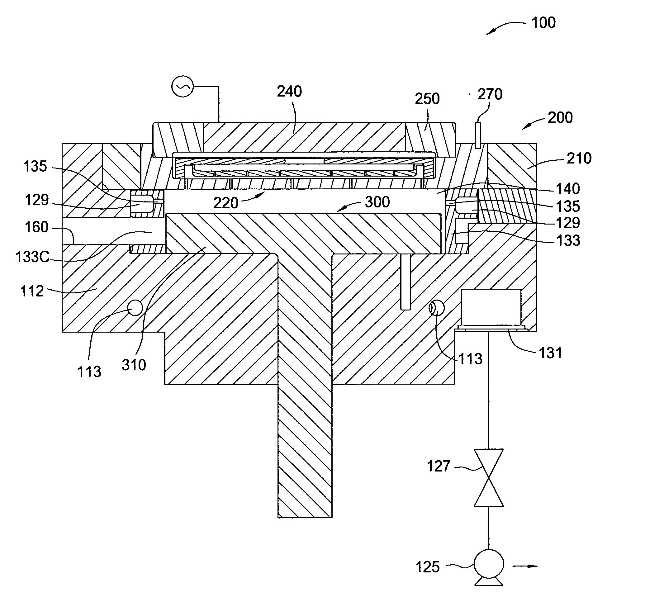
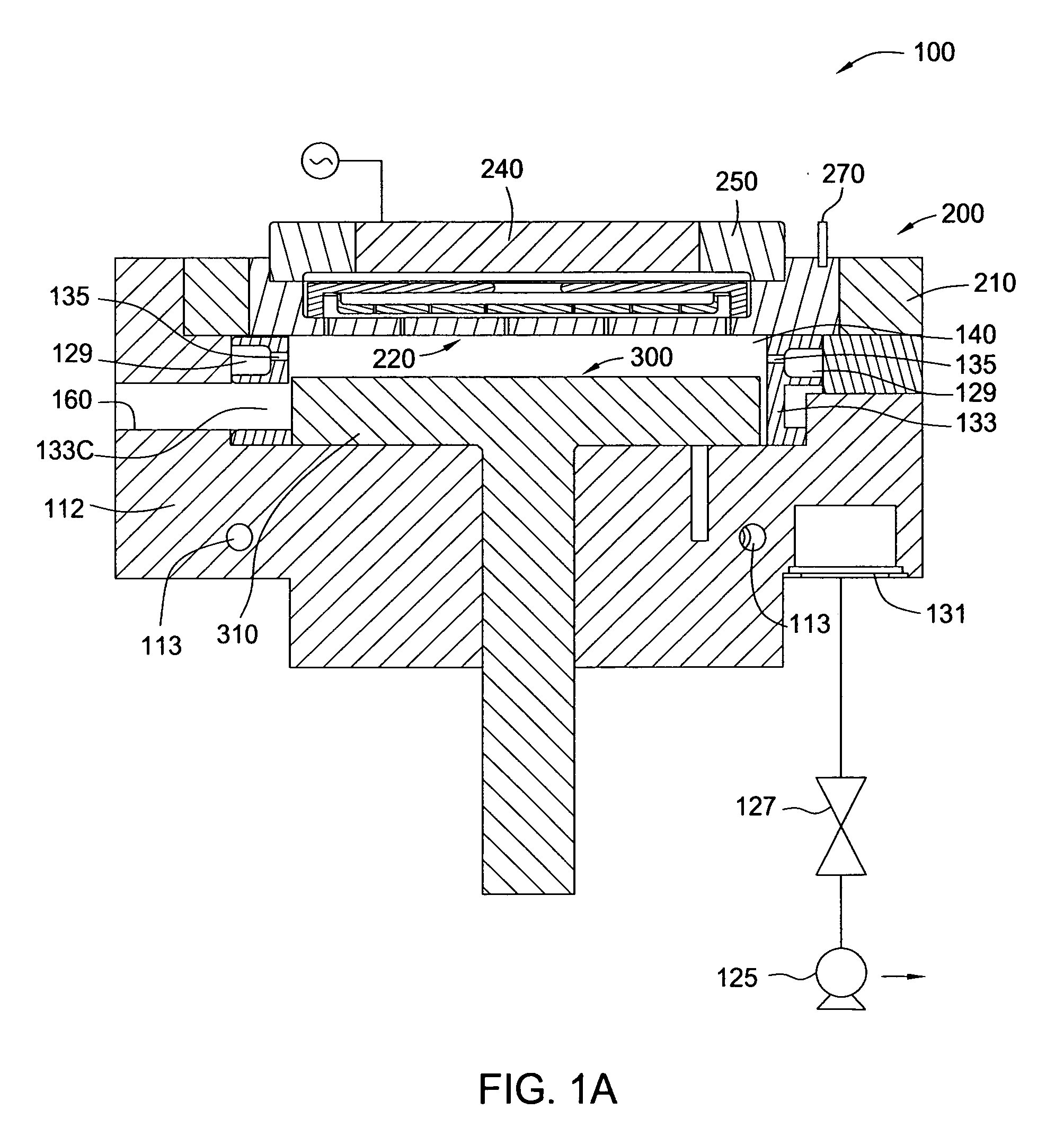
[0120] During etch, a gas mixture of 2 sccm of NF3, 10 sccm of NH3 and 2,500 sccm of argon was introduced into the chamber. A plasma of the gas mixture was ignited using 100 Watts of power. The bottom purge was 1,500 sccm of argon and the edge purge was 50 sccm of argon. The chamber pressure was maintained at about 6 Torr, and the substrate temperature was about 22° C. The substrate was etched for 120 seconds.

[0121] During subsequent annealing, the spacing was 750 mil and the lid temperature was 120° C. The substrate was annealed for about 60 seconds. About 50 angstroms of material was removed from the substrate surface. No anneal effect was observed. The etch rate was about 0.46 angstroms per second (28 Å / min). The observed etch uniformity was about 5% for the 50 Å etch.

[0122] Unless otherwise indicated, all numbers expressing quantities of ingredients, properties, reaction conditions, and so forth, used in the specification and claims are to be understood as approximations. Thes...


PUM

PropertyMeasurementUnit
thickaaaaaaaaaa
thickaaaaaaaaaa
diameteraaaaaaaaaa

Abstract

A lid assembly for semiconductor processing is provided. In at least one embodiment, the lid assembly includes a first electrode comprising an expanding section that has a gradually increasing inner diameter. The lid assembly also includes a second electrode disposed opposite the first electrode. A plasma cavity is defined between the inner diameter of the expanding section of the first electrode and a first surface of the second electrode.

Description

CROSS-REFERENCE TO RELATED APPLICATIONS [0001] This application is a divisional of copending U.S. patent application Ser. No. 11 / 063,645 filed on Feb. 22, 2005, which claims benefit of U.S. provisional patent application Ser. No. 60 / 547,839, filed Feb. 26, 2004, which are herein incorporated by reference.BACKGROUND OF THE INVENTION [0002] 1. Field of the Invention [0003] Embodiments of the present invention generally relate to semiconductor processing equipment. More particularly, embodiments of the present invention relate to a chemical vapor deposition (CVD) system for semiconductor fabrication and in situ dry cleaning methods using the same. [0004] 2. Description of the Related Art [0005] A native oxide typically forms when a substrate surface is exposed to oxygen. Oxygen exposure occurs when the substrate is moved between processing chambers at atmospheric conditions, or when a small amount of oxygen remaining in a vacuum chamber contacts the substrate surface. Native oxides may...

Claims


Application Information

Patent Timeline
Patent Type & Authority Applications(United States)
IPC IPC(8): H01L21/28C23C16/455C23F1/00H01J37/32H01L21/00H01L21/302H01L21/3065H01L21/3205H01L21/8238H01L23/12H01L23/52
CPCH01J37/32082H01J37/32357H01L2924/0002H01J37/32522H01J2237/2001H01L21/67069H01L21/67109H01L21/02104C23C14/022C23C14/50C23C14/541H01J37/3244H01J37/32541H01J37/32568H01J37/32862H01L2924/00H01L21/02334H01L21/0228
Inventor KAO, CHIEN-TEHUMOTOY, SALHUSTON, JOEL M.TRINH, SONCHANG, MEICHANG, YULU, XINLIANGWANG, WEI W.PHAN, SEE-ENG
Owner APPLIED MATERIALS INC
Why Eureka
Try Eureka