Process for the deposition of uniform layer of particulate material

Inactive Publication Date: 2005-10-06
EASTMAN KODAK CO
View PDF24 Cites 23 Cited by
  • Summary
  • Abstract
  • Description
  • Claims
  • Application Information

AI Technical Summary

Benefits of technology

[0017] In accordance with various embodiments, the present invention provides technologies that permit functional material deposition of ultra-small particles; that permits high speed, accurate, and uniform deposition of a functional material on a receiver; that permits high speed, accurate, and precise patterning of a receiver that permits the creation of ultra-small features on the receiver when used in conjunction with a mask; that permits high speed, accurate, and precise coating of a receiver using a mixture of nanometer sized functional material dispersed in dense fluid and where the nanometer sized functional materials are continuously created; that permits high sp

Problems solved by technology

One problem with RESS based thin film deposition technologies is that it is limited only to materials that are soluble in supercritical fluid.
While it is known that co-solvents can improve the solubility of some materials, the class of materials that can be processed with RESS based thin film technologies is small.
Another significant problem is that such technologies fundamentally rely on formation of functional material particles through sudden reduction of local pressure in the delivery system.
While the reduced pressure reduces the solvent power of the supercritical fluid, and causes precipitation of the solute as fine particles, the control of the highly dynamic operative processes is inherently very difficult.
Helfgen et al., in “Simulation of particle formation during the rapid expansion of supercritical solutions”, J. of Aerosol Science, 32, 295-319(2001), discuss how the nucleation of particles upon supersonic free-jet expansion, and subsequent growth by coagulation at and beyond Mach disk, pose s

Method used


Image

  • Process for the deposition of uniform layer of particulate material
  • Process for the deposition of uniform layer of particulate material
  • Process for the deposition of uniform layer of particulate material

Examples


example 1

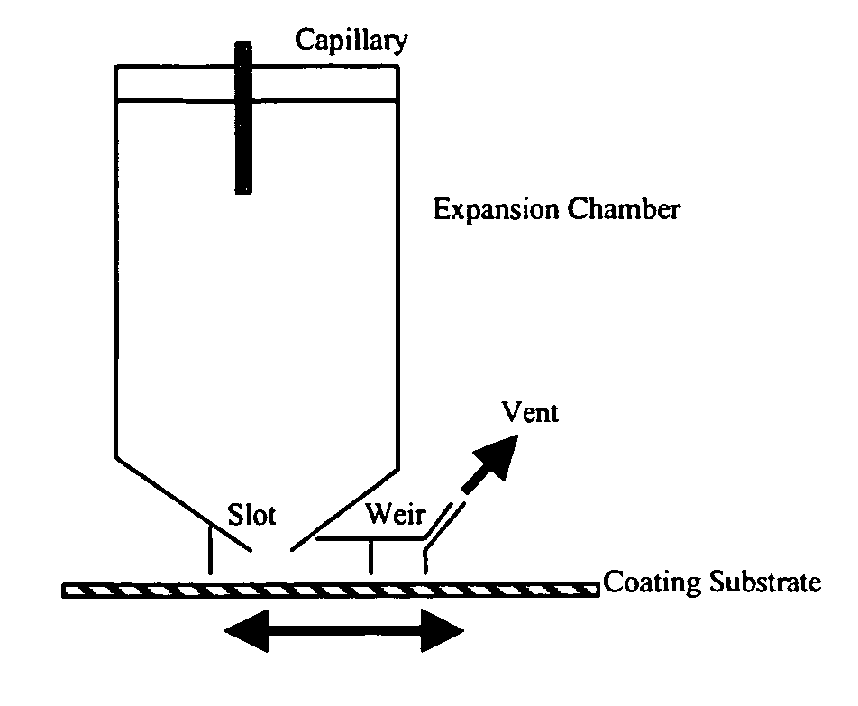
[0042] A nominally 1800 ml stainless steel particle formation vessel was fitted with a 4 cm diameter agitator of the type disclosed in U.S. Pat. No. 6,422,736, comprising a draft tube and bottom and top impellers. CO2 was added to the particle formation vessel while adjusting temperature to 90 C and pressure to 300 bar and while stirring at 2775 revolutions per minute. The addition of CO2 at 60 g / min through a feed port that had a 200 μm orifice at its tip, and a 0.1 wt % solution of Dye E and 0.01 wt % Cellulose Acetate Propionate binder (EASTMAN CAP 480-20) in acetone at 2 g / min, through a 100 μm tip, was then commenced, and the contents of the expansion chamber were exhausted from the chamber through an outlet port at an equivalent rate. The CO2 and solution feed ports were located close to the bottom impeller as disclosed for the inlet tubes for the mixer in U.S. Pat. No. 6,422,736, such that both the solution and the CO2 feed streams were introduced into a highly agitated zone ...

example 2

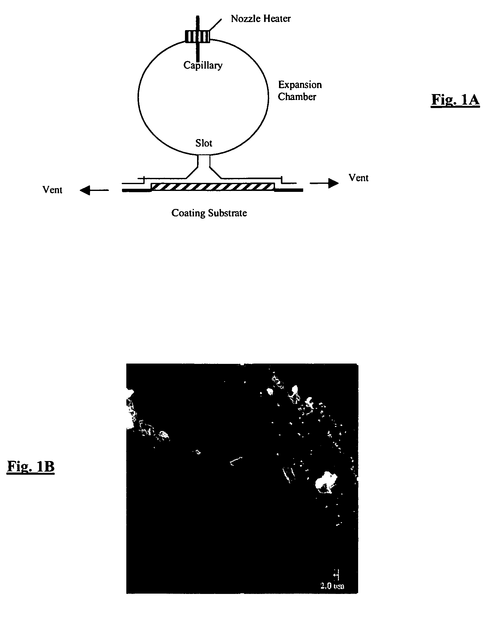
[0045] A nominally 1800 ml stainless steel particle formation vessel was fitted with a 4 cm diameter agitator of the type disclosed in U.S. Pat. No. 6,422,736, comprising a draft tube and bottom and top impellers. CO2 was added to the particle formation vessel while adjusting temperature to 90 C and pressure to 300 bar and while stirring at 2775 revolutions per minute. The addition of CO2 at 40 g / min through a feed port that had a 200 μm orifice at its tip, and a 0.1 wt % solution of Tert-Butyl-anthracene di-naphthylene (TBADN: a functional material used in Organic Light Emitting Diodes) in acetone at 2 g / min, through a 100 μm tip, was then commenced, and the contents of the expansion chamber were exhausted from the chamber through an outlet port at an equivalent rate. The CO2 and solution feed ports were located close to the bottom impeller as disclosed for the inlet tubes for the mixer in U.S. Pat. No. 6,422,736, such that both the solution and the CO2 feed streams were introduced...

example 3

[0048] The procedure employed in Example 2 was repeated, except the functional material concentration was 0.05 wt % in acetone and the pre-expansion heater temperature was 180 C. The resulting coating on the glass slide was also similarly examined, but at a surface magnification of 100×. FIG. 3 shows the instrument signal near a carefully created edge on the deposition surface. The lower level of the signal corresponds to the bare surface. The higher level corresponds to the deposited layer. It shows a nominal layer thickness of 30 nm, and a layer that is also continuous. The average surface roughness of the 30 nm thick layer was 5.44 nm, calculated by WYCO NT1000 as the arithmetic average of the absolute values of the surface features from the mean plane.


PUM


Abstract

A process for the deposition of particulate material of a desired substance on a surface includes: (i) charging a particle formation vessel with a compressed fluid; (ii) introducing into the particle formation vessel a first feed stream comprising a solvent and the desired substance dissolved therein and a second feed stream comprising the compressed fluid, wherein the desired substance is less soluble in the compressed fluid relative to its solubility in the solvent and the solvent is soluble in the compressed fluid, and wherein the first feed stream is dispersed in the compressed fluid, allowing extraction of the solvent into the compressed fluid and precipitation of particles of the desired substance; (iii) exhausting compressed fluid, solvent and the desired substance from the particle formation vessel at a rate substantially equal to the rate of addition of such components to the vessel in step (ii) through a restrictive passage to a lower pressure whereby the compressed fluid is transformed to a gaseous state and a flow of particles of the desired substance is formed; and (iv) exposing a receiver surface to the exhausted flow of particles of the desired substance and depositing a uniform layer of particles on the receiver surface.

Description

FIELD OF THE INVENTION [0001] This invention relates generally to deposition technologies, and more particularly, to a technology for delivering a flow of functional materials that are precipitated as liquid or solid particles into a compressed fluid that is in a supercritical or liquid state and becomes gaseous at ambient conditions, to create a uniform thin film onto a receiver. BACKGROUND OF THE INVENTION [0002] Deposition technologies are typically defined as technologies that deposit functional materials dissolved and / or dispersed in a fluid onto a receiver (also commonly known as substrate etc.). Technologies that use supercritical fluid solvents to create thin films are known. For example, R. D. Smith in U.S. Pat. No. 4,582,731, U.S. Pat. No. 4,734,227 and U.S. Pat. No. 4,743,451 discloses a method involving dissolution of a solid material into a supercritical fluid solution and then rapidly expanding the solution through a short orifice into a region of relatively low pressu...

Claims


Application Information

Patent Timeline
IPC IPC(8): B05D1/00B05D1/04B05D1/06B05D1/12B05D1/26G03C1/74
CPCB05D1/007B05D1/06B05D1/12B05D1/26B05D2401/32B05D2401/90G03C1/74
Inventor MEHTA, RAJESH V.JAGANNATHAN, RAMESHJAGANNATHAN, SESHADRIROBINSON, KELLY S.POND, KAREN L.HOUGHTALING, BRADLEY M.
Owner EASTMAN KODAK CO
Why Eureka
Try Eureka