
Netshape manufacturing processes and compositions

a manufacturing process and composition technology, applied in the field of energy production, can solve the problems of reducing reducing the efficiency of energy production, so as to achieve the effect of improving the energy density of products and lowering the maximum energy density

Inactive Publication Date: 2005-10-13
NEW JERSEY INSTITUTE OF TECHNOLOGY
View PDF5 Cites 3 Cited by
  • Summary
  • Abstract
  • Description
  • Claims
  • Application Information

AI Technical Summary

Benefits of technology

The present invention is a clean and cost-saving manufacturing process for producing energetic products with improved uniformity and higher energy density. The process involves combining particulate coating and handling steps to create free-flowing particles that can be easily introduced into munitions and achieve optimal packing density. The invention eliminates the need for laminar mixing, which is conventionally used but results in inhomogeneous products with lower energy density. The invention also provides techniques for coating and granulation of particles, as well as specifying different combinations of clustered, granulated, or coated particles for achieving specific packing conditions. Overall, the invention offers a safer and more efficient way to manufacture energy products.

Problems solved by technology

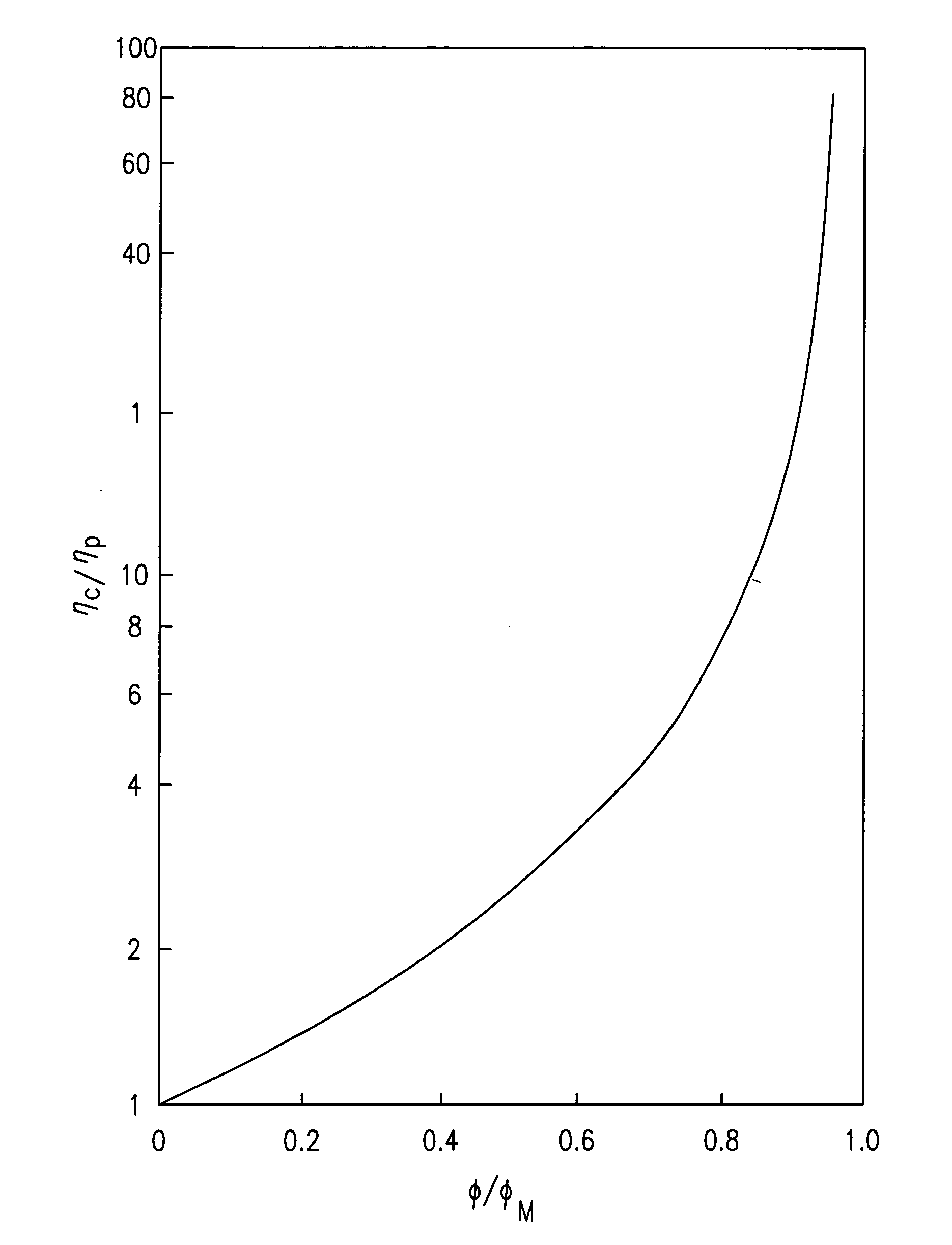
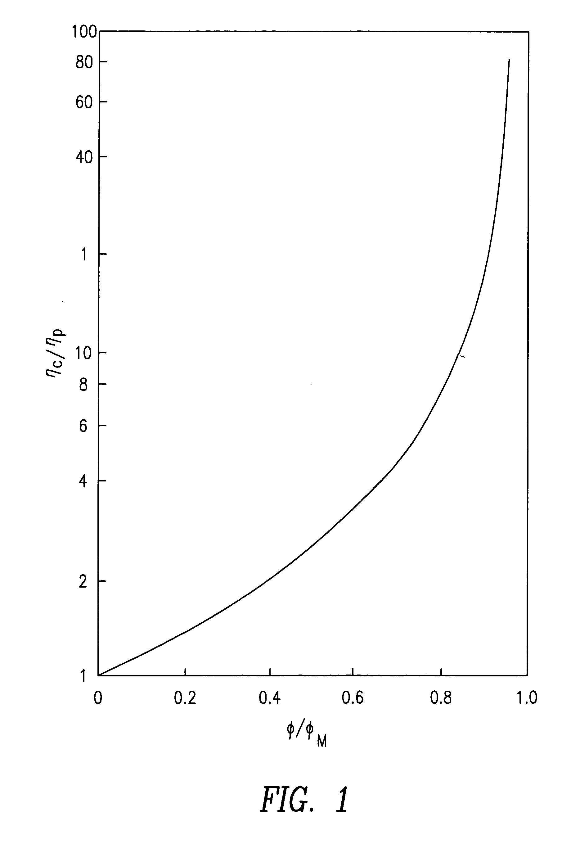
In order to meet the constant demand to improve the energy density, the conventional energetics manufacturing process has been pushed to the limit due to its inability to overcome its fundamental constraint, e.g., the “need to flow in order to mix”.
As a result, energetic products at high solid loadings are often inhomogeneous, and, since the mixing quality performance is intractable, always require destructive testing methods for quality assurance.
Furthermore, the ongoing efforts toward the increasing use of smaller energetic particles in order to enhance munitions insensitivity are also hindered by the limitation of conventional mixing equipment to handle highly viscous mixing media resulting from the enormous increase of particle surface area and the resulting dramatic viscosity increases of the “charge”.
Also, mixing of otherwise desirable small size particles causes an undesirable viscosity increase.
The high viscosity of the mixture requires substantial torque to blend.
The power required to mix, combined with long mixing times, result in inefficient mixing and high power consumption, leading to potentially undesirable and dangerous heat buildup.
Attempting to mix faster can result in an unacceptable temperature rise in the batch.
To date, no prior art mechanism has been established that yields ordered adhesion.
In the pharmaceutical industry, any addition of binder / glue in the ordered mixing process to enhance the adhesion between small drug particles and coarser carrier particles will reduce the dissolution rate and thus the bioavailability of the final dosage form.
As a result, the relatively weak interactive forces between the guest (drug) and host (carrier excipient) particles tend to segregate by frictional attrition during subsequent solids handling and processing steps.
An ordered system has a greater stability than a random system due to the particle interaction; but once this interaction is disturbed, the segregation pattern of an ordered mixture may be more unpredictable than a random mixture.
The inventive processes replace cumbersome, century-old processes which are currently used to produce energetic products, which force highly-filled, rheologically complex fluid systems under high stress, high temperature laminar mixing flows, resulting in energetic products which are often inhomogeneous and of appreciably lower than maximum energy density.

Method used


Image

  • Netshape manufacturing processes and compositions
  • Netshape manufacturing processes and compositions
  • Netshape manufacturing processes and compositions

Examples


example 2

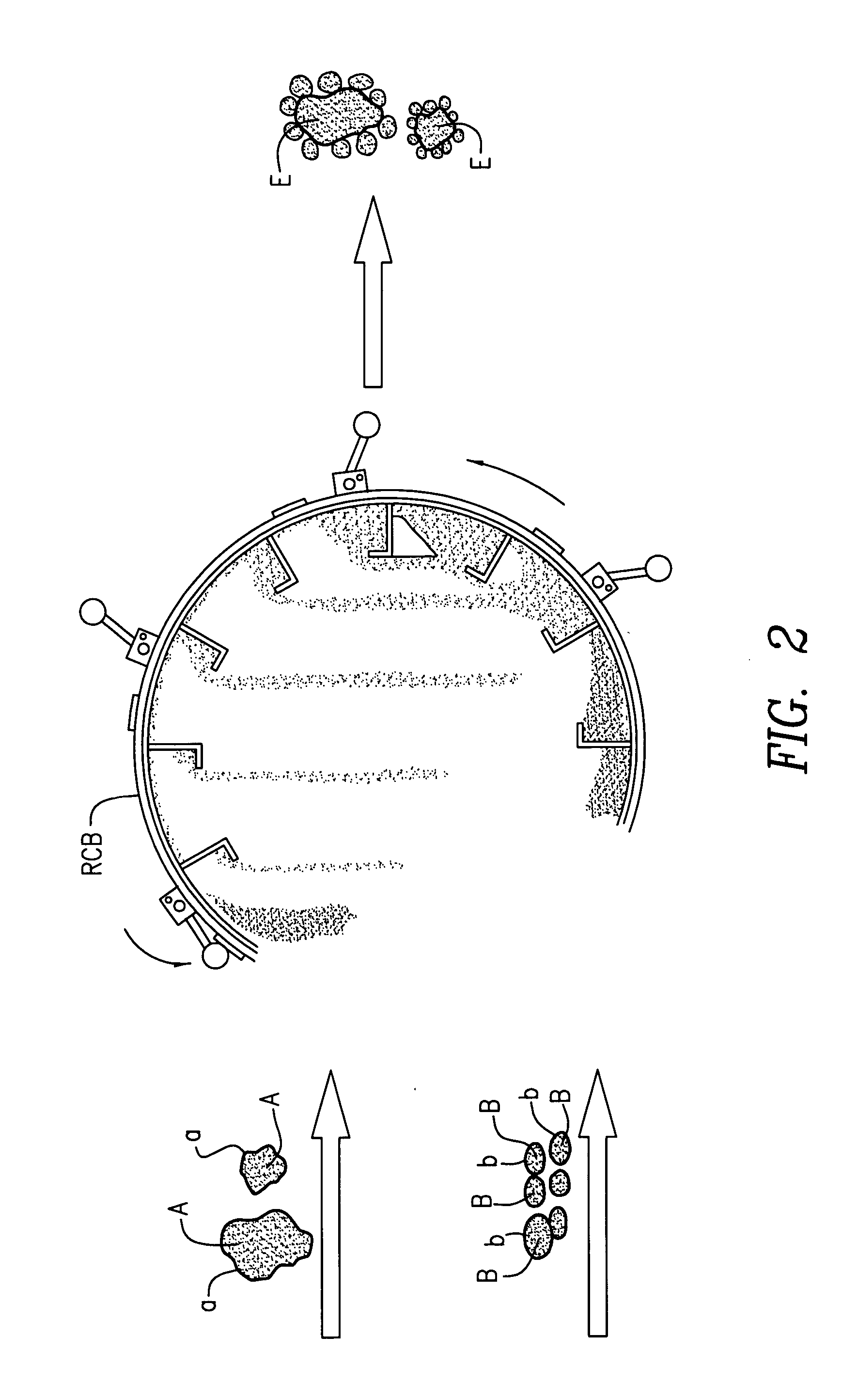
[0125] Particle A is acetaminophen and B is powdered poly(vinyl acetate). The oppositely charged polymer particles surround and agglomerate on the drug. The formulation is employed to modulate the pharmacological release of the active drug.

[0126] The advantages of triboelectric clustering according to the present invention are that no viscous liquid binder is required, mixing and filling are simplified, A and B are in close proximity, the combined powders A and B are flowable and there is a degree of control of the proportions of B to A (“stoichiometry”).

[0127] Magnetic Clustering

[0128] As is well known, a collection of iron particles can be magnetized and will adhere to one another. This is an unstructured array of one type of particle. Typically, the powder becomes an agglomerate and does not flow. This is undesirable for the present invention which seeks a flowable bicomponent powder. Magnetic particles with permanent magnetic moments (ferrites, iron powder, etc.) attract one ...

example 1

[0131]“A” is a 100 μm diameter particle of barium ferrite. “B” is an organic polymer containing or coated with numerous nanoparticles of SPM ferrous ferrite, Fe3O4.

[0132] The barium ferrite is premagnetized, and thus retains a remnant magnetism. This is the attractor for particles of B which cluster around the A particle, held by magnetostatic forces.

[0133] If A is not an intrinsically magnetic material, it can be coated with a layer of attached material containing a ferrimagnet such as barium ferrite.

[0134] Magnetic clustering in accordance with the foregoing method can be used to combine A and B into a dry flowable composite suitable for the manufacture of many materials including energetics and explosives.

[0135] Chemical Reaction or Fusion

[0136] Now referring to FIG. 7, clustering may be achieved by heating a charge of different sized particles A and B and polymer D above the glass transition temperature of the coated polymer to form fusion points 10 between particles. Alter...


PUM

PropertyMeasurementUnit
bimodal size distributionaaaaaaaaaa
sizeaaaaaaaaaa

Abstract

Techniques and processes that combine particulate coating processes with particulate handling steps resulting in the formation of free-flowing particulates for introduction into energetic product vessels to affect an in-situ, net-shape manufactured product. The processes involve selecting suitably sized materials, processing such materials such that they are surface-coated and / or locally “structured” particulates, and pouring, preferably “dry” pouring, these processed materials into an energetic product vessel and infusing the filled vessel with a polymerizable and surface-compatible monomer or oligomer which flows into the unoccupied volume, followed by polymerization of the monomer, which then becomes the binder giving mechanical integrity to the final, net-shape energetic composition.

Description

FIELD OF THE INVENTION [0001] The present invention relates to the manufacture of energetics and in particular to methods for preparing novel compositions and net-shape manufactured energetic products having enhanced compositional homogeneity, higher energetic loading density and safer handling properties. BACKGROUND [0002] Melt pour energetic compositions are currently made by blending various energetic ingredients with a low viscosity binder in a mixer. In order to meet the constant demand to improve the energy density, the conventional energetics manufacturing process has been pushed to the limit due to its inability to overcome its fundamental constraint, e.g., the “need to flow in order to mix”. As a result, energetic products at high solid loadings are often inhomogeneous, and, since the mixing quality performance is intractable, always require destructive testing methods for quality assurance. Furthermore, the ongoing efforts toward the increasing use of smaller energetic par...

Claims


Application Information

Patent Timeline
Patent Type & Authority Applications(United States)
IPC IPC(8): C06B21/00C06B45/02C08J3/20C08K7/00C10L5/00D03D23/00
CPCC06B21/0025C06B21/0083C06B45/02C08J3/20
Inventor GOGOS, COSTASYOUNG, MING-WANDAVE, RAJESHPFEFFER, ROBERTTODD, DAVIDQIAN, BAINIANDAVIDSON, THEODORE
Owner NEW JERSEY INSTITUTE OF TECHNOLOGY
Learn More