
Implantable heart assist system and method of applying same

a heart assist and implantable technology, applied in the field of extracardiac pumping system, can solve the problems of exertional dyspnea (difficult or laborious breathing), inability to maintain continuous flow, and nearly 250,000 patients per year to achieve the effect of revitalizing blood and low amount of energy inpu

Inactive Publication Date: 2005-11-17
TC1 LLC
View PDF99 Cites 16 Cited by
  • Summary
  • Abstract
  • Description
  • Claims
  • Application Information

AI Technical Summary

Benefits of technology

The present invention is an extracardiac pumping system for improving the condition of patients with CHF. It is designed to be a simple and effective heart assist system that can be applied in a minimally invasive procedure. The system uses an extracardiac pump to supplement the circulation of blood through the patient without connecting to the heart or primary vessels. It has the ability to pump blood at subcardiac rates, which can revitalize the blood to a certain extent by imparting kinetic and potential energy to it. The system is also designed to reduce the pumping load on the heart, potentially allowing it to recover. The invention can be applied at a single cannulated site or multiple sites, and it can be used in a continuous or pulsatile flow format. Overall, the invention offers a simple and effective solution for improving the condition of patients with CHF.

Problems solved by technology

Unfortunately, nearly 250,000 patients die of heart failure annually.
CHF manifests itself primarily by exertional dyspnea (difficult or labored breathing) and fatigue.
Under these circumstances, however, continuous flow may not be desired because the patient's arterial system is deprived of pulsatile wave flow, which is beneficial to certain parts of the patient.
If it is not operated in direct synchronization with the patient's heart, there is a risk that the pump might cause “carotid steal phenomenon” where blood is drawn away from the patient's brain through the carotid arteries when there is insufficient blood in the left ventricle.
Moreover, they do not operate as a continuous flow system, operating exclusively in pulsatile fashion.
Of course, with any system that includes an oxygenator, such as the conventional heart-lung machine, the patient cannot be ambulatory.
Inflation and deflation of the balloon, however, requires a pneumatic pump that is sufficiently large that it must be employed extracorporeally, thereby restricting the patient's movements and ability to carry out normal, daily activities.
IABP devices are, thus, limited to short term use, on the order of a few days to a few weeks.
With such systems, extreme pumping and large amounts of energy, volume, and heat dissipation are required.
Due to having one or more of these features, the prior art heart assist devices are limited in their effectiveness and / or practicality.
Noncompliance with what is often a complex drug regime may dramatically adversely affect the recovery of a CHF patient leading to the need for hospitalization and possibly morbidity and mortality.
In addition, ACE inhibitors and diurectics can cause hypotension, which leads to decreased organ perfusion or an increasing demand on the heart to pump more blood.
This leads to an inability, in many cases, to prescribe the most effective dosage of ACE inhibitors and a less than optimum outcome for the patient.
When blood flow through the coronary arteries falls below the level needed to provide the energy necessary to maintain myocardial function, due often to a blockage in the coronary arteries, a myocardial infarction or heart attack occurs.
The closer the blockage is to the coronary ostia, however, the more severe and life threatening the myocardial infarction.
The larger the area that dies due to the loss of oxygen, the more devastating the infarction.
Unloading the left ventricle decreases the energy requirements of the myocardium and increases the amount of time before irreversible damage occurs.
The disadvantage, however, is that each of these techniques can only be performed in an emergency room or hospital setting.
Unless the patient is already in the hospital when the myocardial infarction occurs, there is usually some level of irreversible damage and subsequent loss of myocardial function.
While there may be advantages to using such devices to treat congestive heart failure, there is the disadvantage that it is difficult to determine how far to squeeze the ventricle and / or heart to restore it to its normal size.
Moreover, the heart walls are already stressed and enlarged upon the application of such devices.

Method used


Image

  • Implantable heart assist system and method of applying same
  • Implantable heart assist system and method of applying same
  • Implantable heart assist system and method of applying same

Examples


first embodiment

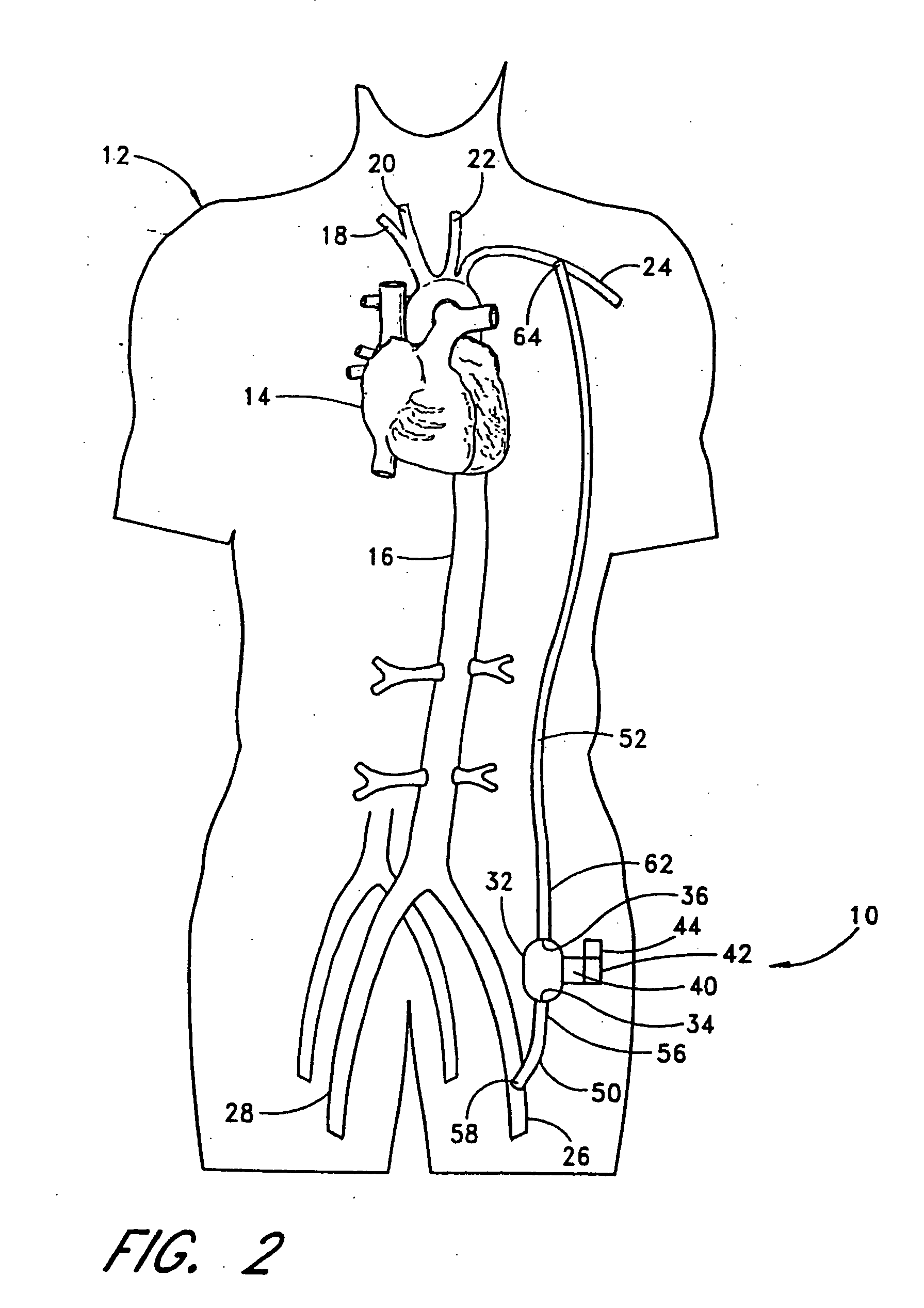
[0061] With reference to FIG. 2, the present invention 10 is shown applied to a patient 12 having an ailing heart 14 and an aorta 16, from which peripheral brachiocephalic blood vessels extend, including the right subclavian 18, the right carotid 20, the left carotid 22, and the left axillary 24. Extending from the descending aorta is another set of peripheral blood vessels, the left and right femoral arteries 26, 28.

[0062] The first embodiment 10 comprises a pump 32, having an inlet 34 and an outlet 36 for connection of flexible conduits thereto. The pump 32 is preferably a rotary pump, either an axial type or a centrifugal type, although other types of pumps may be used, whether commercially-available or customized. In either case, the pump should be sufficiently small to be implanted subcutaneously and preferably extrathoracically, for example in the groin area of the patient, without the need for major invasive surgery. Because the present invention is an extracardiac system, no...

second embodiment

[0078] It is contemplated that, where an anastomosis connection is not desired, a special connector may be used to connect the conduits 50, 52 to the peripheral blood vessels. With reference to FIG. 3, the present invention is shown, wherein the inflow conduit 50 and outflow conduit 52 are connected to the peripheral blood vessels via first and second connectors 68, 70 each comprising three-opening fittings. In the preferred embodiment, the connectors 68, 70 comprise an intra-vascular, generally-tee-shaped fitting 72 having a proximal end 74, a distal end 76, and an angled divergence 78 permitting connection to the inflow and outflow conduits 50, 52 and the blood vessels. The proximal and distal ends 74, 76 of the fittings 72 permit connection to the blood vessel into which the fitting is positioned. The angle of divergence 78 of the fittings 72 may be 90 degrees or less in either direction from the axis of flow through the blood vessel, as optimally selected to generate the needed ...

third embodiment

[0084] A partial external application of the present invention is contemplated where a patient's heart failure is acute; i. e., is not expected to last long, or in the earlier stages of heart failure (where the patient is in New York Heart Association Classification (NYHAC) functional classes II or III). With reference to FIGS. 5 and 10, the present invention 110 is applied percutaneously to a patient 112 to connect two peripheral blood vessels wherein a pump 132 and its associated driving means and controls are employed extracorporeally. The pump 132 has an inflow conduit 150 and an outflow conduit 152 associated therewith for connection to two peripheral blood vessels. The inflow conduit 150 has a first end 156 and second end 158 wherein the second end is connected to a first peripheral blood vessel (e. g., femoral artery 126) by way of a cannula 180. The cannula 180 has a first end 182 sealably connected to the second end 158 of the inflow conduit 150. The cannula 180 also has a ...


PUM


Abstract

An extracardiac pumping for supplementing the circulation of blood, including the cardiac output, in a patient without any component thereof being connected to the patient's heart, and methods of using same. One embodiment provides a vascular graft that has a first end that is sized and configured to couple to a non-primary blood vessel and a second end that is fluidly coupled to a pump to conduct blood between the pump and the non-primary blood vessel. An outflow conduit is also provided that has a first end sized and configured to be positioned within the same or different blood vessel, whether primary or non-primary, through the vascular graft. The outflow conduit is fluidly coupled to the pump to conduct blood between the pump and the patient. The vascular graft may be connected to the blood vessel subcutaneously to permit application of the extracardiac pumping system in a minimally-invasive procedure.

Description

RELATED APPLICATIONS [0001] This application is a continuation-in-part of U.S. application Ser. No. 10 / 171,023, filed on Jun. 11, 2002, which is a continuation-in-part of U.S. application Ser. No. 10 / 078,260, filed on Feb. 15, 2002, which is a continuation-in-part of U.S. application Ser. No. 09 / 552,979, filed on Apr. 21, 2000, now U.S. Pat. No. 6,390,969 B1, which is a continuation-in-part of U.S. application Ser. No. 09 / 470,841, filed on Dec. 23, 1999, now U.S. Pat. No. 6,387,037 B1, which is a continuation-in-part of U.S. application Ser. No. 09 / 289,231, filed on Apr. 9, 1999, now U.S. Pat. No. 6,428,464 B1, which is continuation-in-part of U.S. application Ser. No. 09 / 1665005, filed on Oct. 2, 1998, now U.S. Pat. No. 6,200,260 B1, which claims the benefit of U.S. Provisional Application Ser. No. 60 / 061,434, filed Oct. 9, 1997, all of which are hereby expressly incorporated by reference herein in their entirety.FIELD OF THE INVENTION [0002] The present invention relates generally...

Claims


Application Information

Patent Timeline
Patent Type & Authority Applications(United States)
IPC IPC(8): A61M1/10A61M1/12A61M1/36A61M25/00A61M39/10
CPCA61M1/10A61M1/122A61M1/107A61M1/12A61M1/3621A61M1/3653A61M1/3655A61M25/0026A61M25/003A61M25/007A61M2230/04A61M1/1005A61M1/1008A61M1/1034A61M1/101A61M1/3659A61M60/414A61M60/274A61M60/232A61M60/859A61M60/237A61M60/569A61M60/117A61M60/861A61M60/152A61M1/3623A61M60/148A61M60/178
Inventor BOLLING, STEVEN F.VIOLE, ANTHONYO'LEARY, SHAWN
Owner TC1 LLC
Learn More