[0011] The present invention adopts a novel, all-optical approach in
beam control / deflection / tracking techniques based on combination of optical wave
phase conjugation and optical dynamic
holography. The
advantage of this approach is that it allows achieving automatic, self-controlled
coupling of beam emitters and receivers (e.g. optical fibers or distant telecommunication satellites). The proposed approach is based on using
nonlinear optical materials, in which the so-called
Double Phase Conjugation (DPC, also known as mutual
phase conjugation, or double-pumped
phase conjugation) can be realized with low
light intensity. Combining the DPC phenomenon with dynamically recorded
diffraction grating in these materials allows a bi-directional
optical link to be established between a
transmitter and a
receiver with an automatic tracking feature. The concept eliminates the need for ultra-precise mechanical steering elements as well as complicated positioning and addressing computing. One of the important results is the potential increase in the performance levels of both the ground
optical fiber and intersatellite communication links.
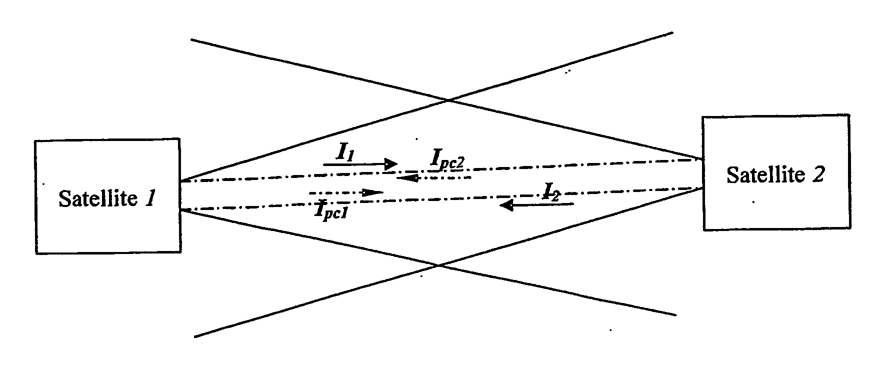
[0012] Accordingly in a first aspect the present invention provides a method of establishing bi-directional self-tracking optical communication through
free space between first and second optical communication devices, comprising generating at said first and second optical communication devices respective first and second outgoing beams, each of said first and second outgoing beams comprising a
signal beam and a
pilot beam; diverging said first outgoing beam and transmitting said divergent first outgoing beam from said first optical
communication device toward said second optical
communication device, and diverging said second outgoing beam and transmitting said divergent second outgoing beam from said second optical
communication device toward said first optical communication device; dynamically recording at each of said first and second optical communication devices a
holographic grating with said first and second outgoing beams thereby creating a phase conjugated version of said first outgoing beam at said second optical communication device and a phase conjugated version of said second outgoing beam at said first communication device; returning said phase conjugated version of said first outgoing beam to said first optical communication device, and returning said phase conjugated version of said second outgoing beam to said second optical communication device such that said phase conjugated versions of said first and second outgoing beams track said respective first and second optical communication devices and contribute to the recording of said holographic gratings through
positive feedback; and effecting
information transfer between said optical communication devices over said signal beams reflected off said respective holographic gratings at each of said optical communication devices.
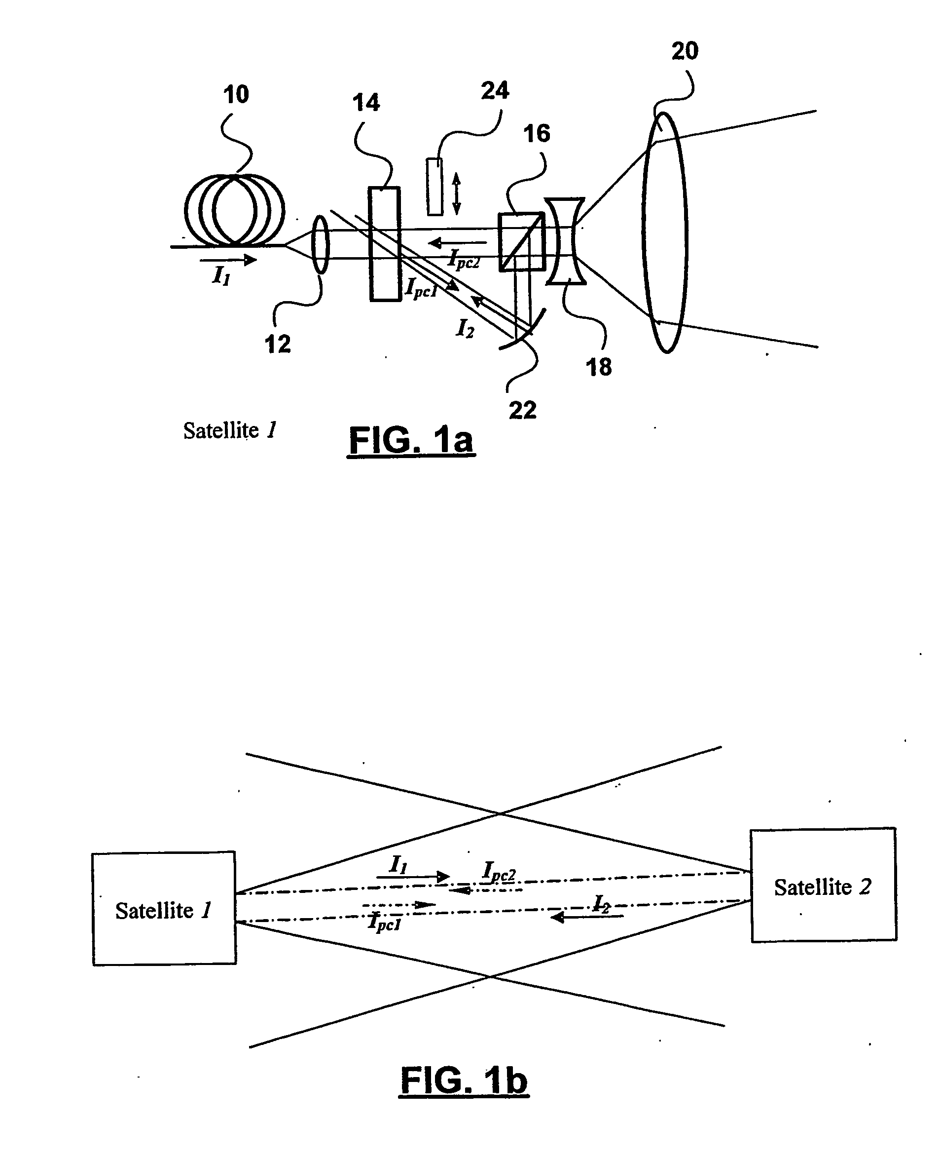
[0018] In another aspect the present invention provides an optical communication device for use in a
system for optical bi-directional self-tracking communication through free space comprising a pair of optical communication devices, said optical communication device comprising a single-mode
fiber for combining a
pilot beam and a
signal beam to create a combined outgoing beam; an output element for diverging said outgoing beam so that said divergent output beam can propagate through free space toward the other optical communication device; a non-linear optical element in the path of said outgoing beam and an incoming non-phase conjugated beam from the other optical communication device for dynamically recording a
holographic grating that creates a phase conjugated version of said incoming non-phase conjugated beam; and an element for directing an incoming phase conjugated beam that is a phase conjugated version of said outgoing beam created at the other optical communications device toward said non-
linear element so as to enhance said recording of said
holographic grating through
positive feedback; and whereby information can be transferred to the other optical communications device on said
signal beam reflected off said holographic
grating.
[0019] Thus, the invention provides a novel, all-optical approach in
beam control / deflection / tracking techniques based on combination of optical wave phase conjugation and optical dynamic
holography. Such an approach is suitable for achieving automatic, self-controlled
coupling of beam emitters and receivers (e.g. optical fibers or distant telecommunication satellites). The method and the apparatus is proposed, both based on using
nonlinear optical materials, in which the so-called
Double Phase Conjugation (DPC) process can be realized with low
light intensity. Combining the DPC phenomenon with dynamically recorded
diffraction grating in these materials allows the establishment of a bi-directional
optical link between an
optical transmitter and a
receiver with an automatic tracking feature. The invention can eliminate the need for ultra-precise mechanical steering elements as well as complicated positioning and addressing computing. An important result is the potential increase in the performance levels of both the ground
optical fiber and intersatellite communication links.

