Methods for stable and repeatable ion implantation

a plasma ion and repeatable technology, applied in the direction of vacuum evaporation coating, coating, electric discharge tube, etc., can solve the problems of unstable and/or non-repeatable implant conditions, inefficient low energy operation, unstable and/or non-repeatability of implant conditions

Active Publication Date: 2005-11-24
VARIAN SEMICON EQUIP ASSOC INC
View PDF5 Cites 262 Cited by
  • Summary
  • Abstract
  • Description
  • Claims
  • Application Information

AI Technical Summary

Benefits of technology

[0014] According to a sixth aspect of the invention, a plasma ion implantation system comprises a process chamber; a source for producing a plasma in the process chamber; a platen for holding a substrate in the process chamber; a pulse source for generating implant pulses for accelerating ions from the plasma into the substrate; and an implant controller configured for plasma ion implantation of the substrate according to an implant process and for adjusting ion energy during the implant process to at least partially compensate for an undesired effect of interaction between ions being implanted and the substrate.

Problems solved by technology

Beamline ion implanters are typically designed for efficient operation at relatively high implant energies and may not function efficiently at the low energies required for shallow junction implantation.
A surface to be implanted may interact with the ions being implanted in an undesired way.
These effects may cause unstable and / or non-repeatable implant conditions.
These approaches require an additional process step prior to ion implantation of the dopant material and thus reduce throughput.
This approach applies to beamline systems and has a disadvantage of changing the spatial charge distribution of the beam and thus impacting the implant uniformity and the implant defect generation that may be dependent upon instantaneous dose rate.
The beamline approach can also lead to charge neutralization difficulties, as neutralization systems such as an electron flood gun may be optimized for a specific beam current condition.

Method used


Image

  • Methods for stable and repeatable ion implantation
  • Methods for stable and repeatable ion implantation
  • Methods for stable and repeatable ion implantation

Examples


first embodiment

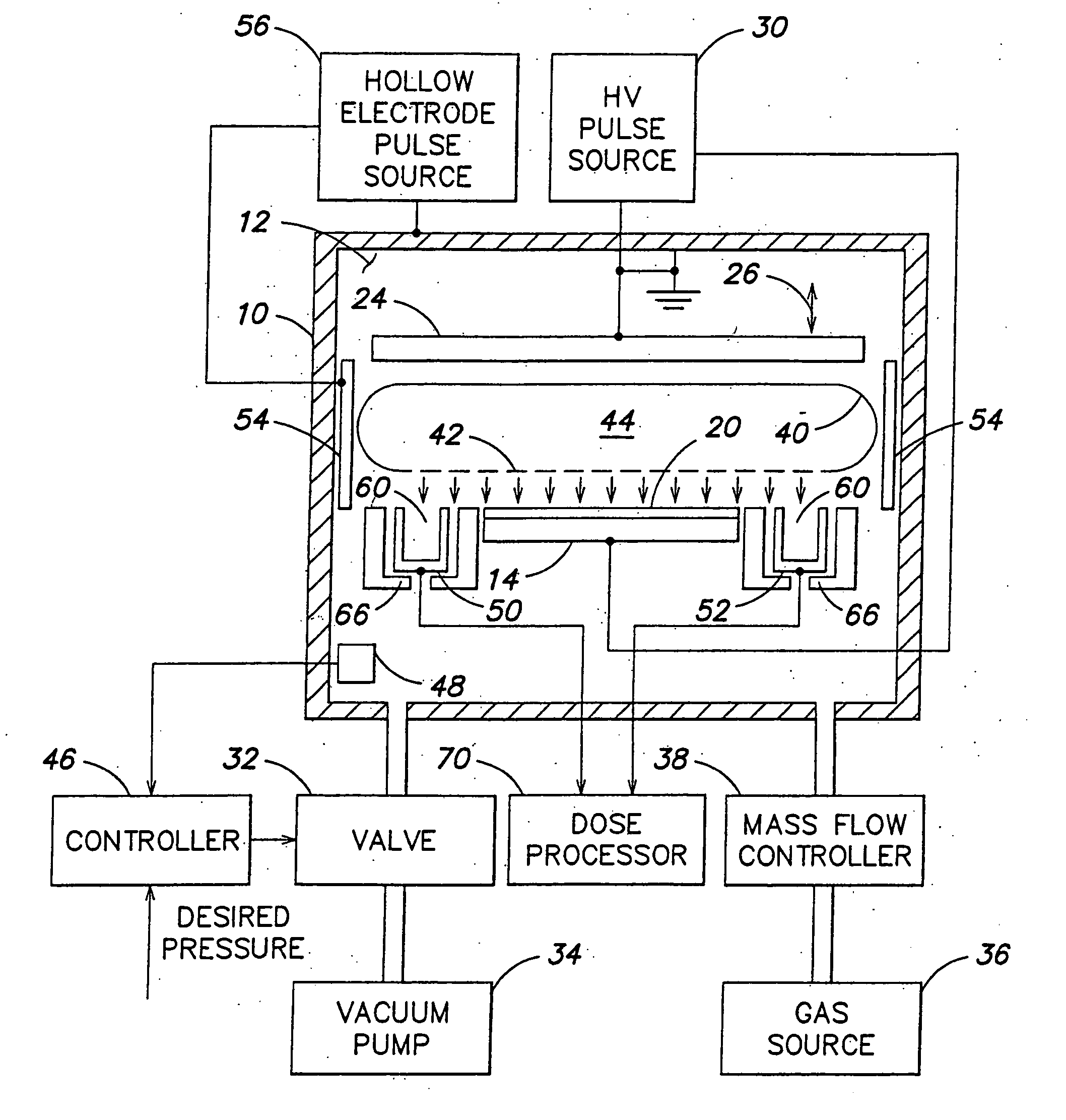
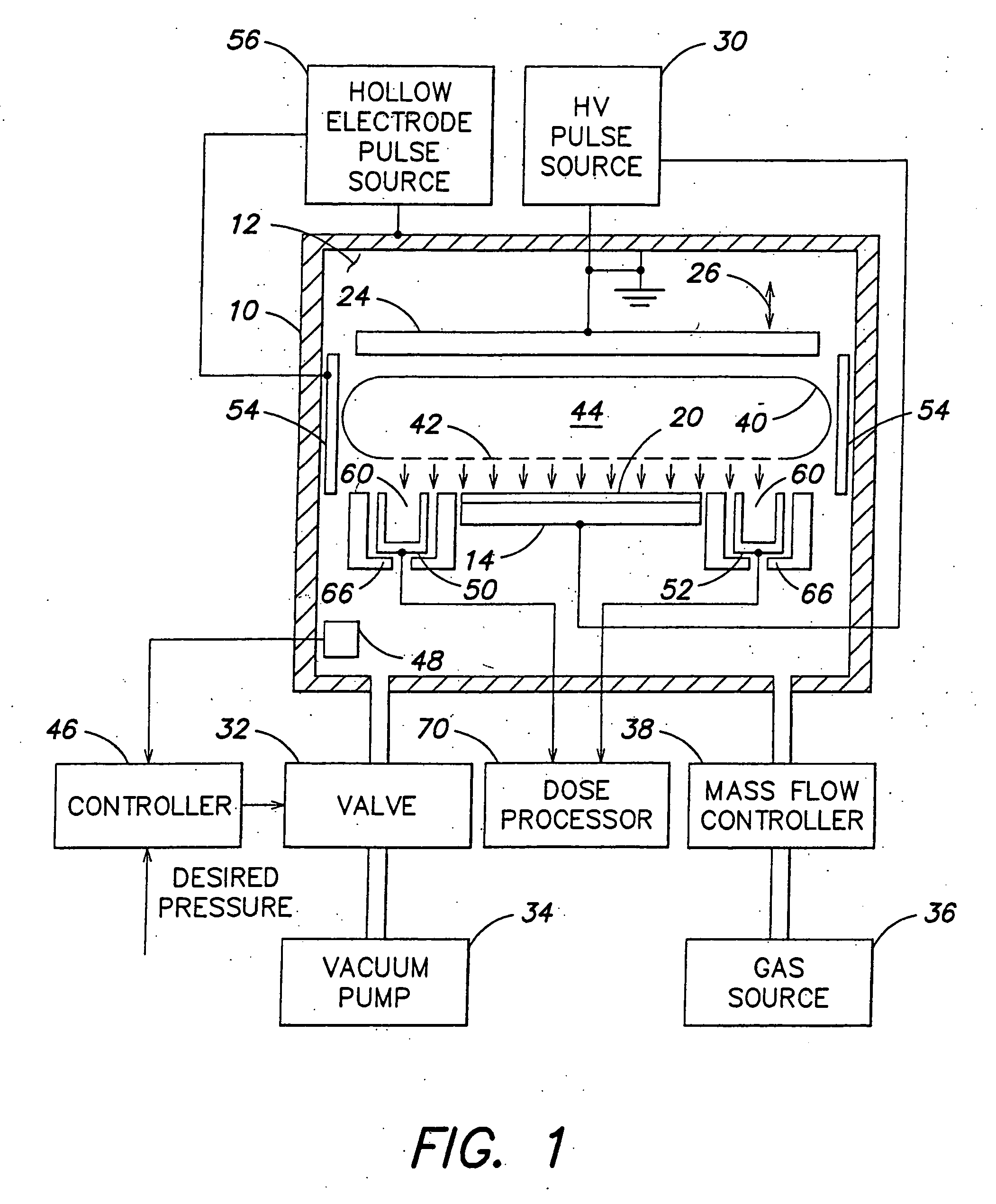
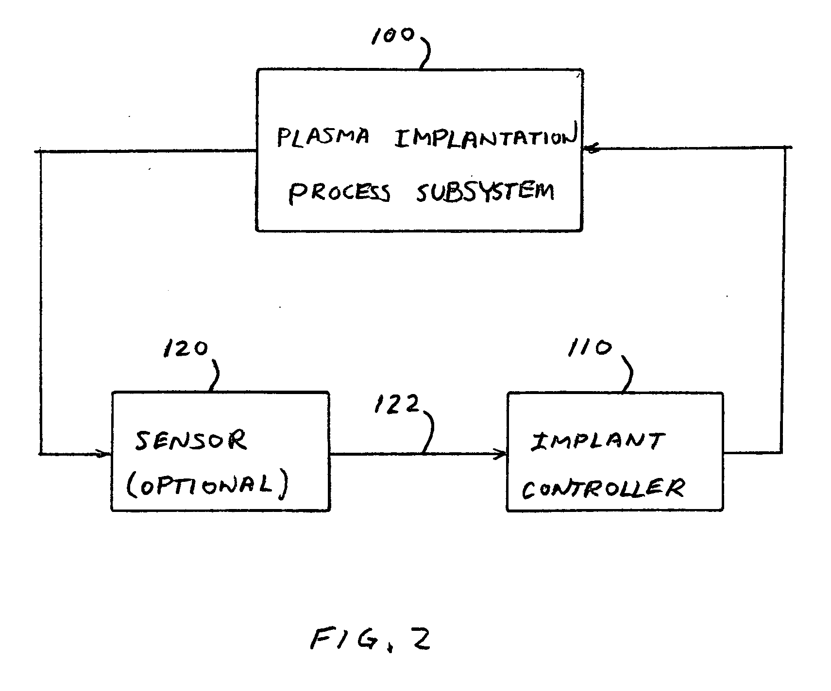
[0035] A simplified schematic block diagram of a plasma ion implantation system in accordance with the invention is shown in FIG. 2. A plasma implantation process subsystem 100 includes some or all of the plasma ion implantation system components shown in FIG. 1, except for process control components. An implant controller 110 controls process subsystem 100 to perform plasma ion implantation in accordance with an implant process.

[0036] The implant process may specify, for example, parameters such as ion species, ion energy, ion dose, dose rate, chamber pressure, implant pulse parameters, and the like. In some embodiments, implant controller 110 operates in an open loop configuration wherein parameters are preprogrammed. The implant parameters may be constant, or one or more of the parameters may have a preprogrammed variation during the implant process. In other embodiments, implant controller 110 may operate in a closed loop configuration wherein at least one optional sensor 120 se...

second embodiment

[0041] A simplified schematic block diagram of a plasma ion implantation system in accordance with the invention is shown in FIG. 3. In the embodiment of FIG. 3, implant controller 110 provides open loop control of pulse source 30 for controlling dose rate, ion energy, or both. By way of example, implant controller 110 may control dose rate according to a preprogrammed implant process. The implant pulse width may be adjusted dynamically to directly control the dose in each pulse by programming of pulse width as a function of time or implant dose. This allows the amount of charge implanted in each implant pulse to be optimized for the implant environment and the substrate surface condition. The pulse repetition frequency may be adjusted in the same manner to allow the time average dose rate to be adjusted. In some embodiments, both the pulse width and the pulse repetition frequency can be adjusted to achieve a desired variation in dose rate. In specific embodiments, the dose rate may...

third embodiment

[0046] A simplified schematic block diagram of a plasma ion implantation system in accordance with the invention is shown in FIG. 5. A system for closed loop control of dose rate and / or ion energy is shown. Sensor 120 senses a parameter of process chamber 10 and provides sensor signal 122 to implant controller 110. In response to the sensor signal 122, implant controller 110 controls one or more parameters of pulse source 30, such as implant pulse width, implant pulse frequency and implant pulse amplitude. Sensor 120 provides feedback from the implant processing environment, such as pressure control parameters, substrate voltage, wafer bias supply current, in-situ charging monitors, optical emission spectroscopy, residual gas analysis, Fourier transform infrared based gas analysis or video analysis of the plasma discharge. It will be understood that one or more sensors may provide sensor signals to implant controller 110. Implant controller 110 may perform an analysis of the sensed ...


PUM

PropertyMeasurementUnit
pressureaaaaaaaaaa
pressureaaaaaaaaaa
voltageaaaaaaaaaa

Abstract

A method for plasma ion implantation of a substrate includes providing a plasma ion implantation system having a process chamber, a source for producing a plasma in the process chamber, a platen for holding a substrate in the process chamber, an anode spaced from the platen, and a pulse source for generating implant pulses for accelerating ions from the plasma into the substrate. In one aspect, a parameter of an implant process is varied to at least partially compensate for undesired effects of interaction between ions being implanted and the substrate. For example, dose rate, ion energy, or both may be varied during the implant process. In another aspect, a pretreatment step includes accelerating ions from the plasma to the anode to cause emission of secondary electrons from the anode, and accelerating the secondary electrons from the anode to a substrate for pretreatment of the substrate.

Description

FIELD OF THE INVENTION [0001] This invention relates to systems and methods for plasma ion implantation of substrates and, more particularly, to methods for at least partially compensating for undesired effects of interaction between ions being implanted and substrates. BACKGROUND OF THE INVENTION [0002] Ion implantation is a standard technique for introducing conductivity-altering impurities into semiconductor wafers. In a conventional beamline ion implantation system, a desired impurity material is ionized in an ion source, the ions are accelerated to form an ion beam of prescribed energy, and the ion beam is directed at the surface of the wafer. Energetic ions in the beam penetrate into the bulk of the semiconductor material and are embedded into the crystalline lattice of the semiconductor material to form a region of desired conductivity. [0003] A well-known trend in the semiconductor industry is toward smaller, higher speed devices. In particular, both the lateral dimensions a...

Claims


Application Information

Patent Timeline
Patent Type & Authority Applications(United States)
IPC IPC(8): C23C14/48H01J37/32H01L21/223H01L21/26H01L21/42
CPCC23C14/48H01L21/2236H01J37/32412H01L21/265
Inventor WALTHER, STEVEN R.FANG, ZIWEITOCCO, JUSTINELLIS, CARLETON F. III
Owner VARIAN SEMICON EQUIP ASSOC INC
Why Eureka
Try Eureka