Optical waveguide and method of manufacture
a technology of optical waveguides and manufacturing methods, applied in the field of optical waveguides, can solve the problems of limiting the application of optical signal processing, the characteristics of waveguide materials used are limited, and the current waveguide materials are limited to siosub>2/sub>, semiconductors, and a small range of nonlinear crystals. the effect of heat, electric field, magnetic field or sound modification of optical properties
- Summary
- Abstract
- Description
- Claims
- Application Information
AI Technical Summary
Benefits of technology
Problems solved by technology
Method used
Image
Examples
embodiment 1
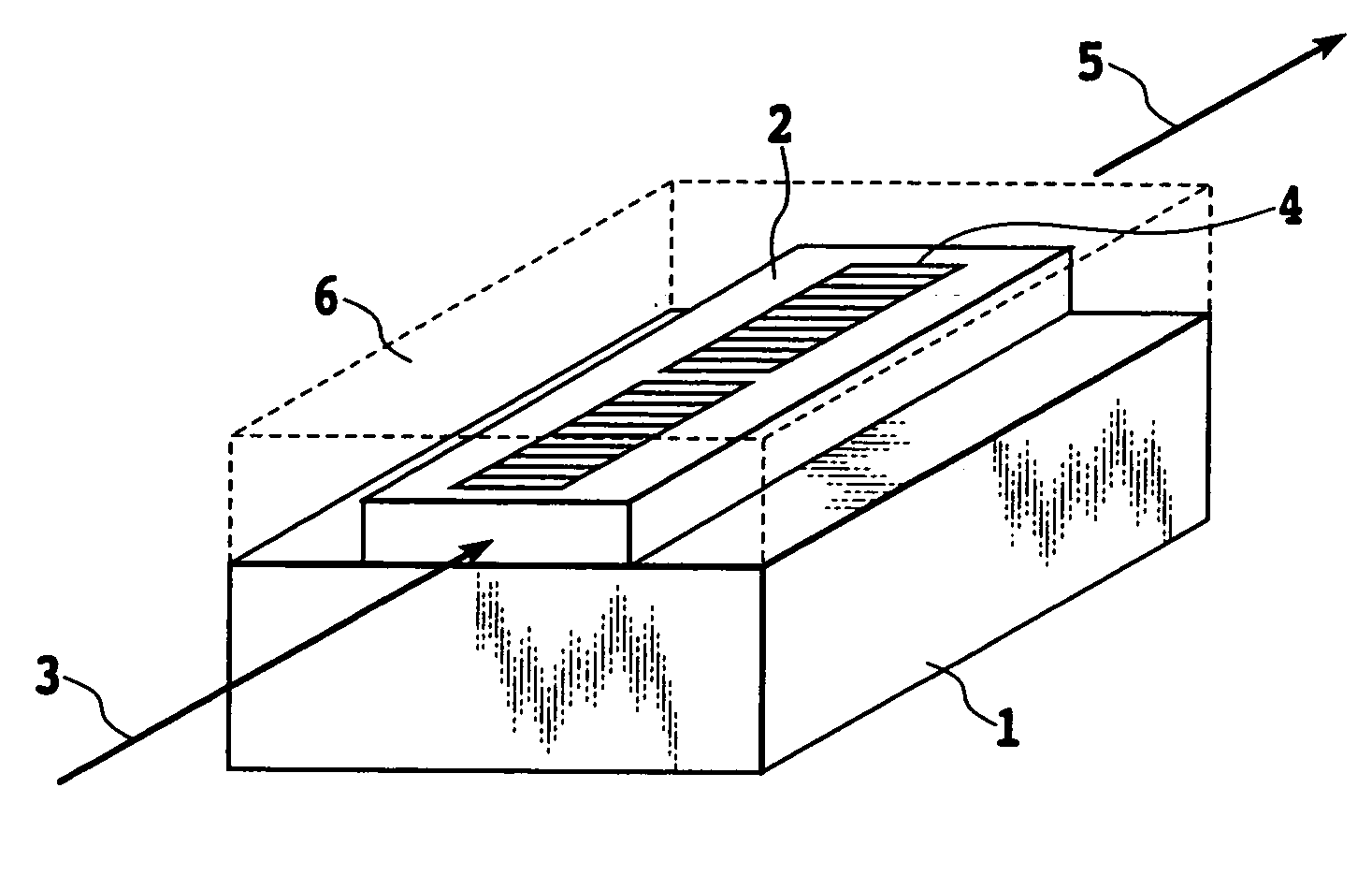
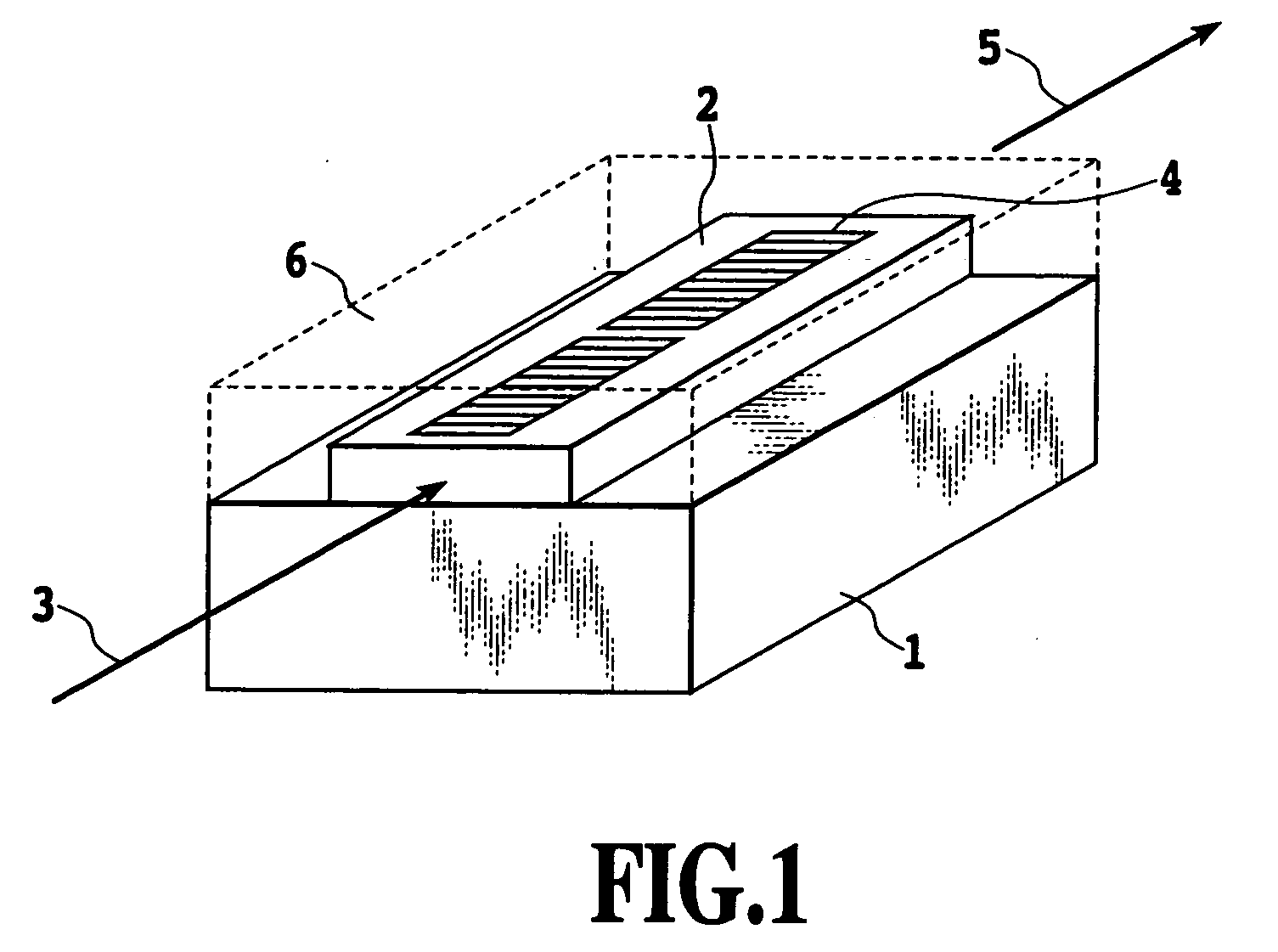
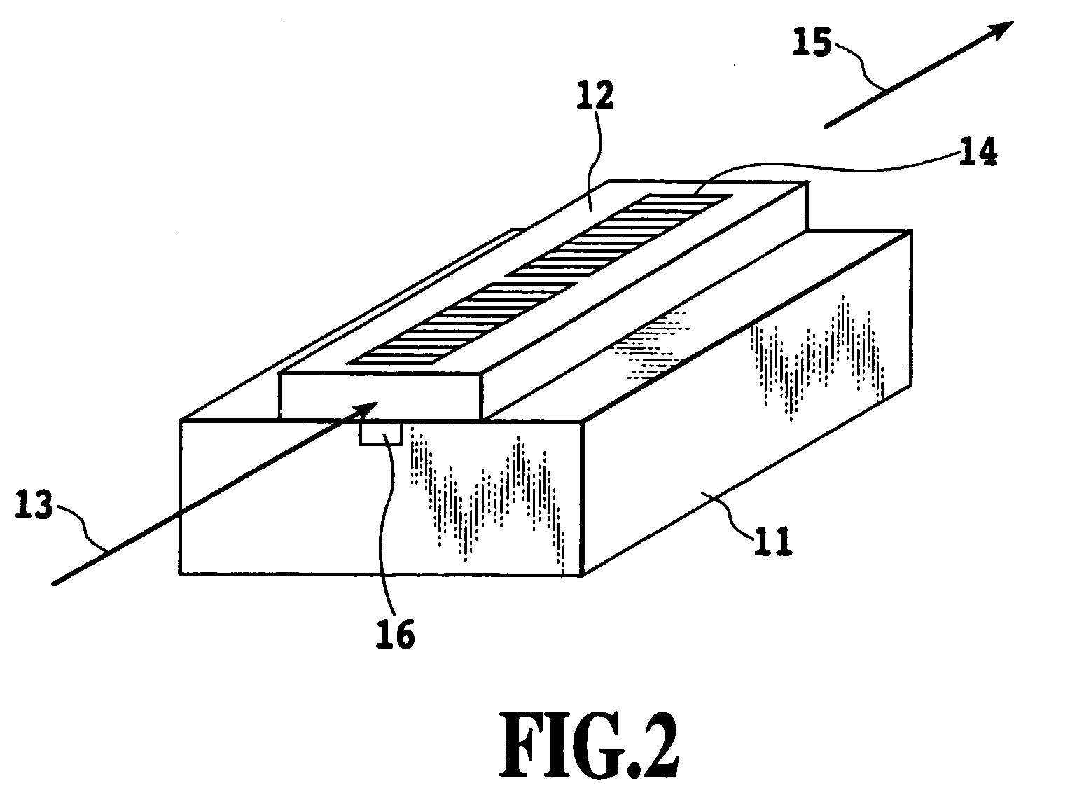
[0065]FIG. 1 is a perspective view showing the fabrication of an optical waveguide applying the present invention. A basic fabrication shown here as an example waveguide structure for explanation uses a ridge type optical waveguide as an optical waveguide and an electric field application from an electrode as an external field application mechanism. In the figure, reference number 1 represents a substrate that functions as an undercladding layer, 2 a waveguide layer having a refractive index higher than that of the substrate 1 and formed from a film of an optical functional material KTaxNb1-xO3 (03 an input optical signal, 4 an electrode, 5 an output optical signal, and 6 an overcladding layer (cover layer) covering the waveguide layer and having a refractive index lower than that of the waveguide layer KTaxNb1-xO3 film 2.
[0066] The input optical signal 3 is transmitted into the KTaxNb1-xO3 film 2. The KTaxNb1-xO3 film 2 changes its optical property by an external voltage signal ap...
embodiment 1-1
[0069] First, the manufacturing process 1 will be explained. In this embodiment, the liquid phase epitaxy capable of forming a single crystal film with high quality was adopted as the method of depositing a high quality KTaxNb1-xO3 film on the substrate 1. A KTaxNb1-xO3 (0≦x≦1) substrate, a MgO substrate, a MgAl2O4 substrate and a NdGaO3 substrate were used for the substrate 1. As the buffer layer (undercladding layer) were used a semiconductor Si substrate, a GaAs substrate and an InP substrate, which were formed by depositing such materials as SiO2, KTaxNb1-xO3 (0≦x≦1), MgO, MgAl2O4 and NdGaO3.
[0070] To prevent a possible contamination, the KTaxNb1-xO3 film 2 was formed by using potassium oxide and KTaxNb1-xO3 oxide as a solvent and a solute, respectively, and by using a self-flux method. As the potassium oxide solvent, a mixture of KVO3 and K2O (KVO3=30-70 mol %) or K2CO3 carbonate was used. When a KTayNb1-yO3 (0≦y≦1) substrate was used, a material with x (01 are shown to have c...
embodiment 1-2
[0074] Next, the manufacturing process 2 will be explained. Photolithography was used to process the KTaxNb1-xO3 film to form a waveguide layer of a ridge type optical waveguide. A resist was applied to the thin film thus formed and was exposed and developed by using a mask for a 2 μm wide waveguide. The material was then etched by an ion milling method and the residual resist was removed, thereby forming a waveguide layer of the ridge type waveguide. The waveguide layer is nearly a 2 μm square and an observation of the side wall using a SEM (scanning electron microscope) found no significantly roughened surface.
[0075] The measurement of loss of this ridge type waveguide at a wavelength of 1.55 μm showed a loss value of 0.99 dB / cm, which means that the waveguide layer formed is good enough so that undulations of the surface as a result of processing can be neglected.
PUM
| Property | Measurement | Unit |
|---|---|---|
| Curie temperature | aaaaa | aaaaa |
| Curie temperature | aaaaa | aaaaa |
| dielectric constant | aaaaa | aaaaa |
Abstract
Description
Claims
Application Information
 - R&D
- Intellectual Property
- Life Sciences
- Materials
- Tech Scout
- Unparalleled Data Quality
- Higher Quality Content
- 60% Fewer Hallucinations
Browse by: Latest US Patents, China's latest patents, Technical Efficacy Thesaurus, Application Domain, Technology Topic, Popular Technical Reports.
© 2025 PatSnap. All rights reserved.Legal|Privacy policy|Modern Slavery Act Transparency Statement|Sitemap|About US| Contact US: help@patsnap.com


