Phenylcarbazole compounds and organic electroluminescence devices using the same

Active Publication Date: 2006-01-26
SAMSUNG DISPLAY CO LTD
View PDF1 Cites 70 Cited by
  • Summary
  • Abstract
  • Description
  • Claims
  • Application Information

AI Technical Summary

Benefits of technology

[0010] Another embodiment provides a high efficiency, low voltage, high lumina

Problems solved by technology

However, only 25% of singlet state excitons can be utilized for fluorescence, and the luminescence efficiency resulting from fluorescence is limited.
However, the lifetime of the organic EL device is short at 150 hours or less, an

Method used


Image

  • Phenylcarbazole compounds and organic electroluminescence devices using the same
  • Phenylcarbazole compounds and organic electroluminescence devices using the same
  • Phenylcarbazole compounds and organic electroluminescence devices using the same

Examples


synthesis example 1 (

Synthesis of Intermediates for Compound 2)

[0059] Compound 2 was synthesized through reaction pathways illustrated in reaction schemes (1) and (2) below.

Synthesis Of Intermediate A

[0060] 3.344 g (20 mmol) of carbazole was added to 40 mL of 1,3-dimethyl-3,4,5,6-tetrahydro-s(1H)-pyrimidinone, and CuI 0.761 g (4 mmol) of Cul, 11.057 g (80 mmol) of K2CO3, and 0.1 g (4 mmol) of 18-Crown-6 were added to the mixture. The resultant mixture was stirred at 170° C. for 20 hours, cooled to room temperature, and distilled under reduced pressure to remove the solvent. 100 mL of dichloromethane was added to dissolve the residue and washed several times with water. The washed dichloromethane layer was dried using MgSO4 and dried under reduced pressure to obtain a crude product. The crude product was purified using silica gel column chromatography and recrystallized using hexane to obtain 3.28 g of a solid intermediate A with a yield of 67%.

Synthesis Of Intermediate B

[0061] 2.433 g (10 mmol) of ...

synthesis example 2 (

Synthesis of Compound 2)

[0063] Compound 2, which is also represented by formula (5) in the detailed description and claims, was synthesized as follow.

[0064] 0.221 g (0.614 mmol) of intermediate C and 0.332 g (0.9 mmol) of intermediate B were dissolved in 10 mL of toluene. 0.144 g (1.5 mmol) of t-BuONa, 0.018 g (0.02 mmol) of Pd(dba)2, 0.004˜0.006 g (0.02˜0.03 mmol) of (t-Bu)3P were added to the solution and stirred at 90° C. for 6 hours. An organic layer was extracted from the reaction solution three times with 30 mL of ethyl ether each. The collected organic layer was dried using MgSO4, and the solvent was vaporized. The resulting residue was purified using silica gel column chromatography to obtain 0.236 g of Compound 2 with a yield of 64%. The structure of Compound 2 was identified by 1H-NMR: 1H-NMR (CDCl3, 400 MHz) δ (ppm) 8.05 (d, 2H), 8.03 (dd, 2H), 7.58 (m, 8H), 7.47 (m, 2H), 7.39 (m, 8H), 7.33 (dd, 2H), 7.24 (m, 2H), 6.94 (d, 2H).

example 1

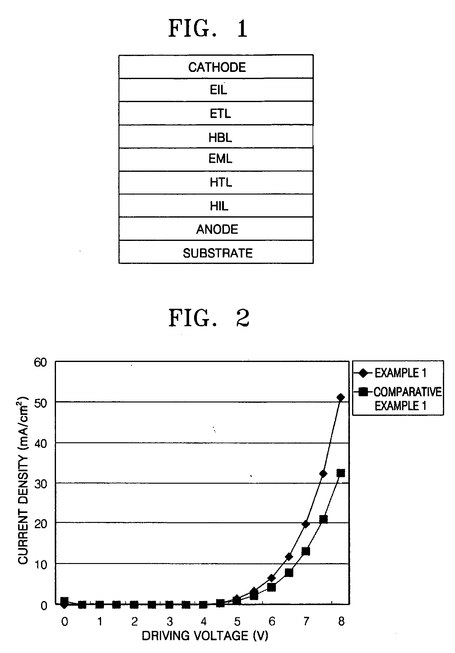
[0065] An indium tin oxide (ITO) substrate (available from Coming Co. (New York, N.Y.)) having a resistance of 15 Ω / cm2 (1200 Å) was cut to a size of 50 mm×50 mm×0.7 mm and washed in isopropyl alcohol and pure water for 5 minutes each by ultrasonication and UV irradiation and using ozone. The washed substrate was loaded into a vacuum deposition apparatus. Initially, a hole injecting layer was formed of IDE 406 on the substrate to a thickness of 600 Å by vacuum deposition. Next, a hole transporting layer was formed on the hole injecting layer by depositing 4,4′-bis[N-(1-naphthyl)-N-phenylamino]biphenyl (NPB) in a vacuum to a thickness of 300 Å. After the formation of the hole transporting layer, an emitting layer was formed by simultaneously depositing on the hole transporting layer Compound 2 as a phosphorescent host and Ir(ppy)3 as a green phosphorescent dopant in a ratio of 93:7 to a thickness of 300 Å. A hole blocking layer was formed on the emitting layer by depositing Balq to a...


PUM

PropertyMeasurementUnit
Percent by massaaaaaaaaaa
Current densityaaaaaaaaaa

Abstract

A phenylcarbazole compound of formula (1) below is provided,
where each of R1 and R2 is independently a monosubstituted or polysubstituted functional group selected from the group consisting of hydrogen atom, a substituted or unsubstituted C1-C30 alkyl group, a substituted or unsubstituted C6-C30 aryl group, a substituted or unsubstituted C4-C30 heterocyclic group, a substituted or unsubstituted C6-C30 condensed polycyclic group, wherein groups adjacent to R1 and R2 bind and form a saturated or unsaturated cyclic hydrocarbon group, and Ar is a substituted or unsubstituted C6-C30 aryl group or a C6-C30 heteroaryl group, wherein the substituent R4 is defined herein. Also included is an organic electroluminescence device comprising the above phenylcarbazole compounds.

Description

CROSS-REFERENCE TO RELATED PATENT APPLICATIONS [0001] This application claims the benefit of Korean Patent Application No. 10-2004-0054700, filed on Jul. 14, 2004, in the Korean Intellectual Property Office, the disclosure of which is incorporated herein in its entirety by reference. BACKGROUND OF THE INVENTION [0002] 1. Field of the Invention [0003] The present invention relates to an organic luminescent compound, and more particularly, to a new luminescent compound that contains at least two phenylcarbazole derivatives in a molecule and can be used in an emitting layer and / or a hole transporting layer of an organic electroluminescence (EL) device, and organic EL device using the compound. [0004] 2. Description of the Related Art [0005] Electroluminescent (EL) devices known as a self-luminous display have the advantages of large viewing angle, high contrast property, and short response time. EL devices can be classified according to the material composing their emitting layer into ...

Claims


Application Information

Patent Timeline
IPC IPC(8): H05B33/12C07D209/82
CPCC07D209/88C07D403/12C09K11/06C09K2211/1029H05B33/14H01L51/0061H01L51/0072H01L51/5012H01L51/5048H01L51/006Y10S428/917H10K85/636H10K85/633H10K85/6572H10K50/14H10K50/11
Inventor HWANG, SEOK-HWANLEE, SEOK-JONGKIM, YOUNG-KOOKYANG, SEUNG-GAKKIM, HEE-YEONLEE, CHANG-HO
Owner SAMSUNG DISPLAY CO LTD
Why Eureka
Try Eureka