Metal-supported tubular fuel cell

a tubular fuel cell, metal-supported technology, applied in the field of fuel cells, can solve the problems of increasing the fragility of the sofc, reducing the wall thickness of the sofc, and not being particularly suitable for small-scale applications

Inactive Publication Date: 2006-03-09
INNOTECH ALBERTA INC
View PDF58 Cites 57 Cited by
  • Summary
  • Abstract
  • Description
  • Claims
  • Application Information

AI Technical Summary

Benefits of technology

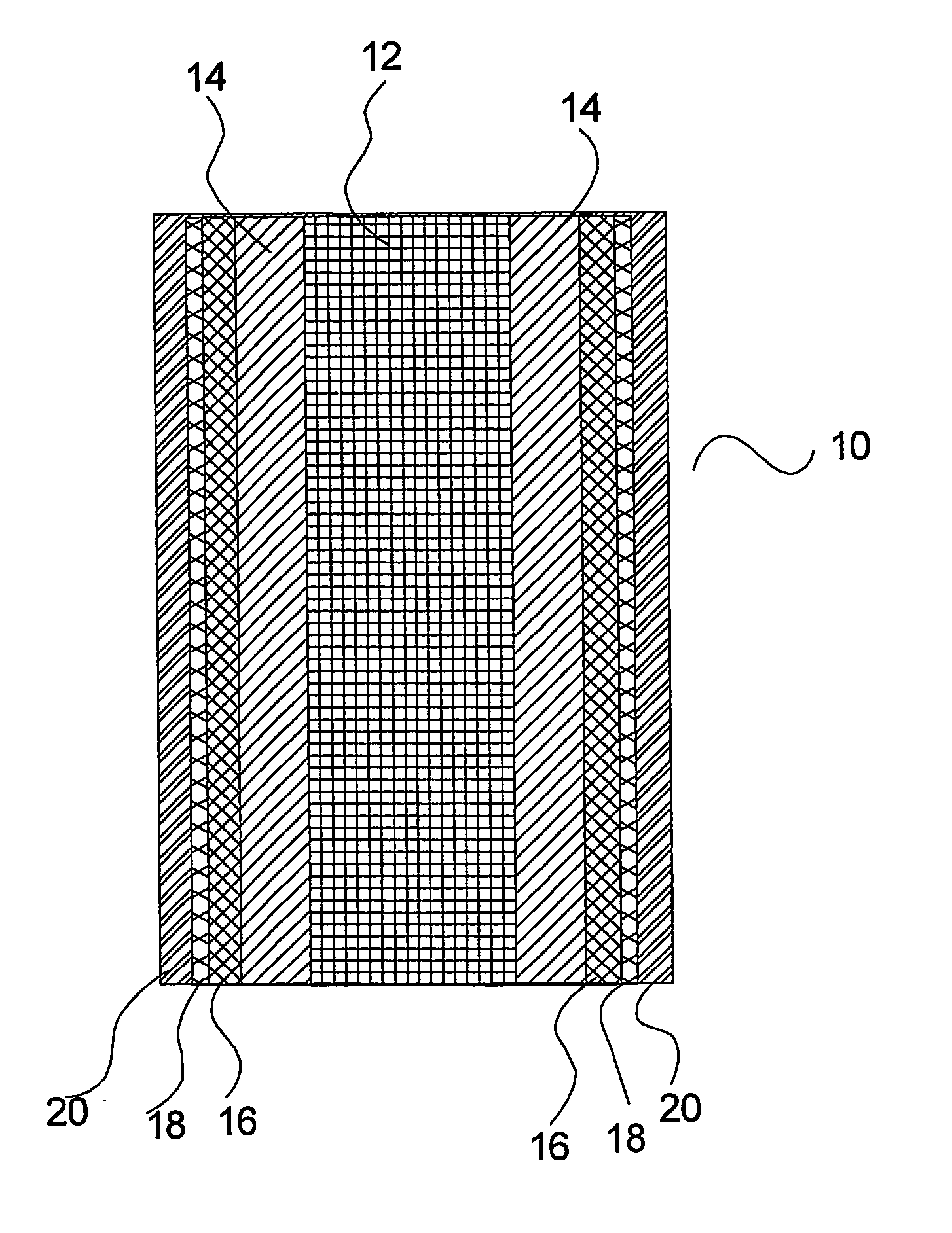
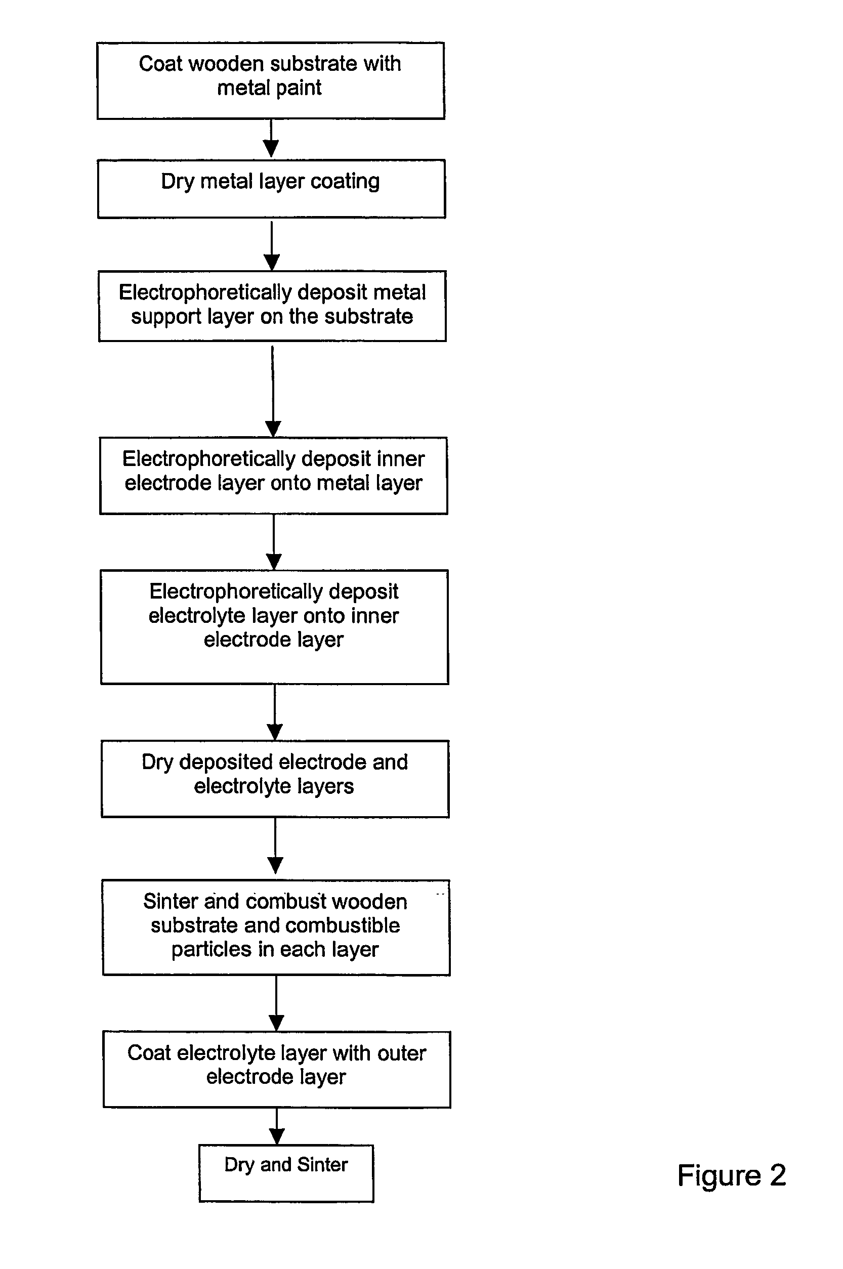
[0029] When the conductive substrate is carbon or graphite or another combustible material, it combusts during sintering. Between steps (a) and (b), the combustible substrate layer can be coated with a substantially metallic support layer by electrophoretic deposition; this support layer lines the inside of the fuel cell. Additionally or alternatively, the outer electrode can be coated with a substantially metallic support layer. The support layer in both cases has sufficient mechanical strength to support the electrode and electrolyte layers during fuel cell operation. In particular, both support layers can have a thickness of between 20 and 500 μm to provide said mechanical strength. Also, both support layers can include combustible additives that combust during sintering to produce a support layer having sufficient porosity to enable the flow of a reactant therethrough.

Problems solved by technology

However, reducing the wall thickness of an SOFC reduces its mechanical strength, and increases its fragility.
Such large-diameter thick-walled SOFC tubes are not particularly suitable for small-scale applications.

Method used


Image

  • Metal-supported tubular fuel cell
  • Metal-supported tubular fuel cell
  • Metal-supported tubular fuel cell

Examples


Embodiment Construction

[0037] When describing the present invention, the following terms have the following meanings, unless indicated otherwise. All terms not defined herein have their common art-recognized meanings.

[0038] The term “ceramic” refers to inorganic non-metallic solid materials with a prevalent covalent or ionic bond including, but not limited to metallic oxides (such as oxides of aluminum, silicon, magnesium, zirconium, titanium, chromium, lanthanum, hafnium, yttrium and mixtures thereof) and nonoxide compounds including but not limited to carbides (such as of titanium tungsten, boron, silicon), silicides (such as molybdenum disicilicide), nitrides (such as of boron, aluminum, titanium, silicon) and borides (such as of tungsten, titanium, uranium) and mixtures thereof; spinels, titanates (such as barium titanate, lead titanate, lead zirconium titanates, strontium titanate, iron titanate), ceramic super conductors, zeolites, and ceramic solid ionic conductors (such as yittria stabilized zirc...


PUM

PropertyMeasurementUnit
thicknessaaaaaaaaaa
thicknessaaaaaaaaaa
thicknessaaaaaaaaaa

Abstract

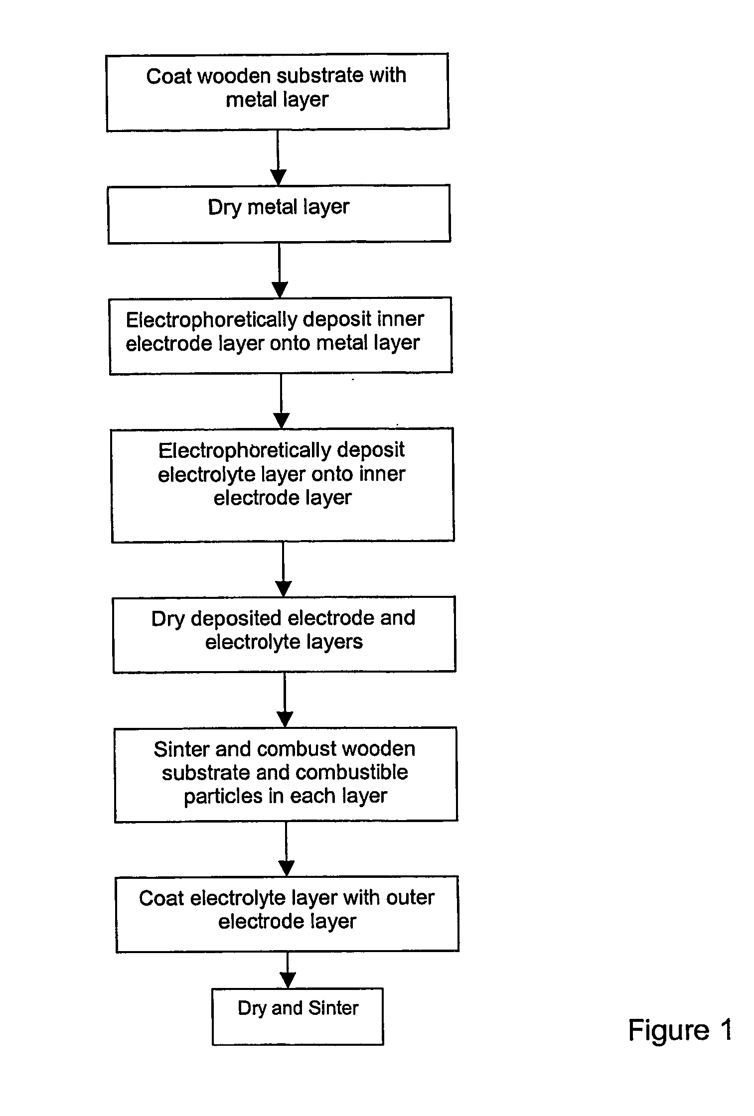
This invention relates to a method of manufacturing a metal-supported tubular micro-solid oxide fuel cell, and a fuel cell made from such method. The method comprises the steps of coating a wooden substrate member with a conductive substrate layer, coating the substrate layer with an inner electrode layer, coating the inner electrode layer with an electrolyte layer, drying and sintering the coated substrate member such that the substrate member combusts, coating the electrolyte layer with an outer electrode layer, and then drying and sintering the layers. The invention further relates to a method of manufacturing a tubular solid oxide fuel cell assembly comprising: a) coating a tubular substantially metallic support layer with a ceramic or cermet inner electrode layer, b) coating the inner electrode layer with a ceramic electrolyte layer; c) coating the electrolyte layer with a ceramic or cermet outer electrode layer, then d) sintering the layers to produce a hollow tubular metal-supported fuel cell; the electrode and electrolyte layers having a collective wall thickness of 80 μm or less, the support layer having sufficient mechanical strength to support the electrode and electrolyte layers and sufficient porosity to flow a reactant therethrough.

Description

FIELD OF THE INVENTION [0001] This invention relates to fuel cells and in particular to metal-supported tubular solid oxide fuel cells, and a method of manufacturing a tubular solid oxide fuel cell on a non-conducting combustible substrate. BACKGROUND OF THE INVENTION [0002] In general, a solid oxide fuel cell (SOFC) comprises a pair of electrodes (anode and cathode) separated by a ceramic, solid-phase electrolyte. To achieve adequate ionic conductivity in such a ceramic electrolyte, the SOFC operates at an elevated temperature, typically between about 750° C. and 1000° C. The material in typical SOFC electrolytes is a fully dense (i.e. non-porous) yttria-stabilized zirconia (YSZ) which is an excellent conductor of negatively charged oxygen (oxide) ions at high temperatures. Typical SOFC anodes are made from a porous nickel / zirconia cermet while typical cathodes are made from magnesium doped lanthanum manganate (LaMnO3), or a strontium doped lanthanum manganate (also known as lantha...

Claims


Application Information

Patent Timeline
Patent Type & Authority Applications(United States)
IPC IPC(8): H01M8/12H01M4/88B05D5/12C04B35/64C04B35/48C04B35/50C04B38/06C25D1/14C25D13/02C25D13/14H01MH01M4/86H01M8/00H01M8/02H01M8/06H01M8/24H01M50/48H01M50/483H01M50/486
CPCC04B38/06Y02E60/525C25D13/02C25D13/14H01M4/8621H01M4/8885H01M4/9066H01M8/0252H01M8/0291H01M8/0612H01M8/1213H01M8/1226H01M8/1253H01M8/126H01M8/243H01M8/2475H01M8/2485H01M2008/1293Y02E60/521C25D1/14H01M8/0289Y02E60/50Y02P70/50H01M8/02H01M8/12
Inventor SARKAR, PARTHORHO, HONGSANGJOHANSON, LORNEYAMARTE, LUIS
Owner INNOTECH ALBERTA INC
Why Eureka
Try Eureka