System and method for optical coherence imaging

Active Publication Date: 2006-03-16
THE GENERAL HOSPITAL CORP
View PDF99 Cites 194 Cited by
  • Summary
  • Abstract
  • Description
  • Claims
  • Application Information

AI Technical Summary

Benefits of technology

[0008] According to the present invention, an imaging apparatus/system is provided which includes an optical source and at least one detector array. In one exemplary embodiment of the present invention, an optical source can emit a broadband spectrum in a pulsed mode, for example, by Q-switching or mode locking, with a pulse repetition rate preferably being equal to a readout rate of a detector array. The pulsed source can produce enough average optical power to provide sufficient signal to noise ratio required for imaging, while the relatively short duration of the output pulses results in an effective signal integration time substantially shorter than the detector's integration time, leading to high-sensitivity motion-artifact-free imaging. This pulsed-source approach may pertain to full-field optical coherence tomography and/or spectral-domain optical coherence tomography. In another exemplary embodiment of the present

Problems solved by technology

Image artifacts resulting from motion have been important issues of research in many medical imaging modalities because they may degrade the image quality and cause inaccurate clinical interpretation of images.
In this case, a path length change in the interferometer during image acquisition results in phase drift in the interference fringe.
If the phase drifts over more than μ during a single A-lin

Method used


Image

  • System and method for optical coherence imaging
  • System and method for optical coherence imaging
  • System and method for optical coherence imaging

Examples


Example

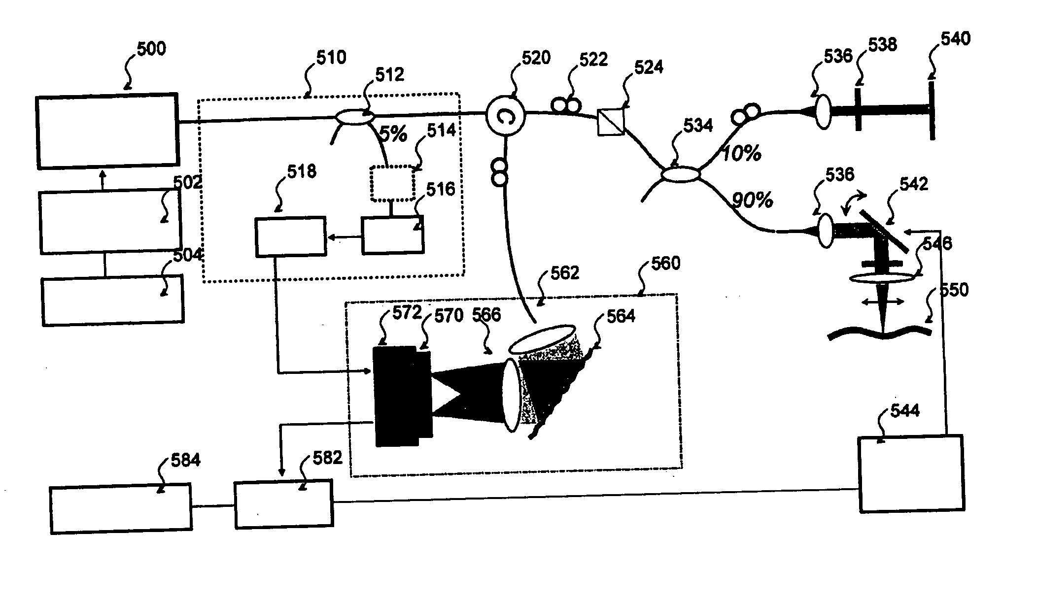
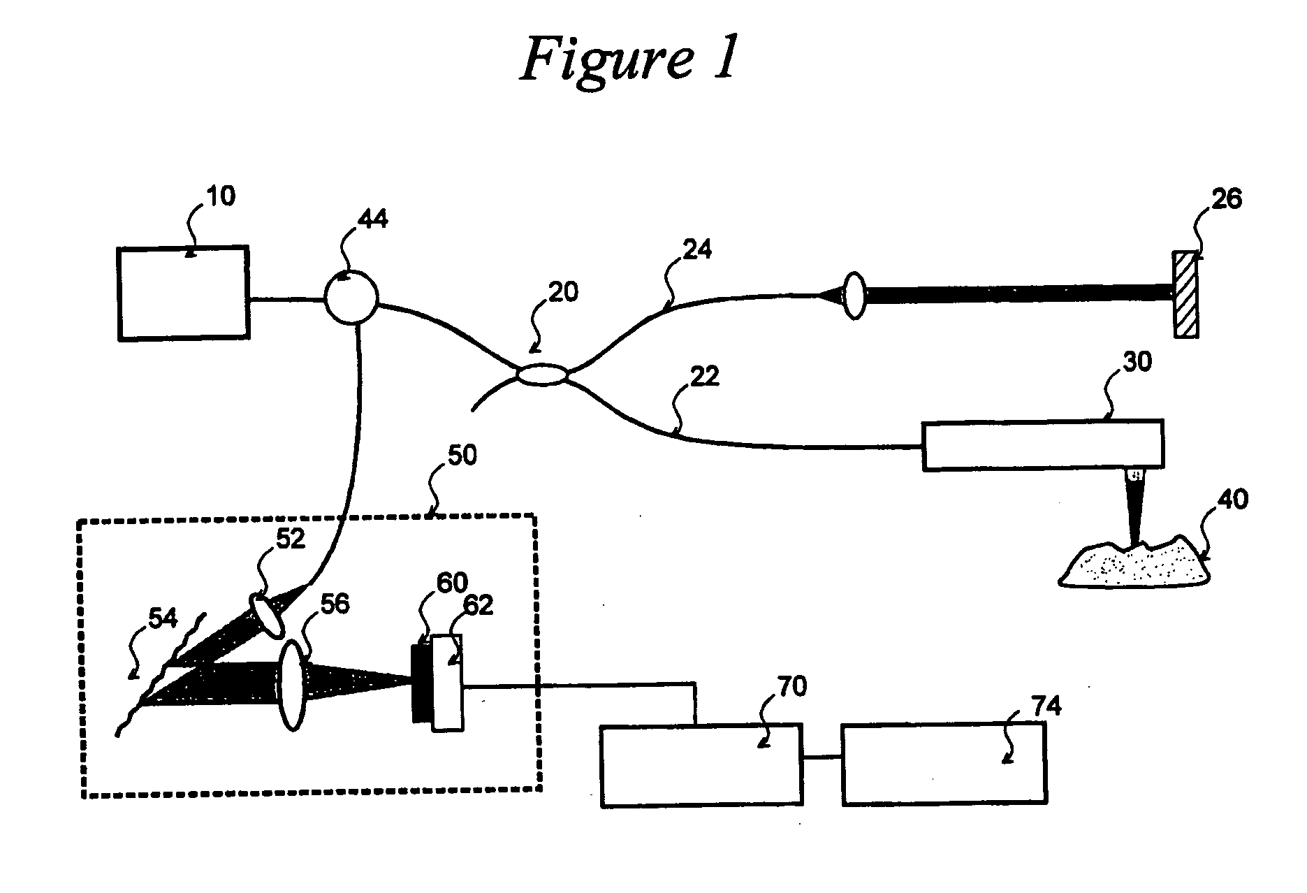
[0037]FIG. 1 depicts an exemplary basic configuration of a spectral-domain optical coherence tomography (“SD-OCT”) system. Broadband light 10 is split by a coupler 20 into a sample arm 22 and a reference arm 24 that is terminated by a mirror 26 at its distal end. A probe 30 at the end of the sample arm delivers light to a sample 40, and receives the light backscattered from within the sample. The light returned from the two interferometer arms is recombined and directed via a circulator 44 to a spectrometer 50 consisting of a collimator 52, a diffraction grating 54, and a lens 56, a CCD array 60, and camera 62. Individual pixels of the CCD array 60 measure the optical power as a function of wave number, k=2π / λ where λ is the optical wavelength. The CCD output is digitized using a digitizer 70 and processed in a computer 74. A discrete Fourier transform (“DFT”) of the CCD scan output produces an axial reflectance profile of the sample (A-line). A 2-D tomographic image can be obtained...


PUM


Abstract

A system and method for imaging of a sample, e.g., biological sample, are provided. In particular, at least one source electro-magnetic radiation forwarded to the sample and a reference may be generated. A plurality of detectors may be used, at least one of the detectors capable of detecting a signal associated with a combination of at least one first electro-magnetic radiation received from the sample and at least one second electro-magnetic radiation received from the reference. At least one particular detector may have a particular electrical integration time, and can receive at least a portion of the signal for a time duration which has a first portion with a first power level greater than a predetermined threshold and a second portion immediately preceding or following the first portion. The second portion may have a second power level that is less than the predetermined threshold, and extends for a time period which may be, e.g., approximately more than 10% of the particular electrical integration time.

Description

CROSS-REFERENCE TO RELATED APPLICATION(S) [0001] The present invention claims priority from U.S. patent application Ser. No. 60 / 608,800 filed on Sep. 10, 2004, the entire disclosure of which incorporated herein by reference.FIELD OF THE INVENTION [0002] The present invention relates generally to optical coherence tomography imaging, and more particularly, to a system and method that uses optical coherence tomography that permits imaging of biological samples with high sensitivity and reduced artifacts, e.g., due to sample and probe motion. BACKGROUND OF THE INVENTION [0003] Image artifacts resulting from motion have been important issues of research in many medical imaging modalities because they may degrade the image quality and cause inaccurate clinical interpretation of images. Artifacts can arise when an object being imaged (sample) is moved during data acquisition but is assumed stationary in the image reconstruction process. In each imaging modality, motion artifacts can be pr...

Claims


Application Information

Patent Timeline
IPC IPC(8): G01B9/02
CPCG01N21/4795G01B9/02004G01B9/02044G01B9/02091G01B2290/45G01B9/02069G01B2290/70G01B9/02077G01B9/02014G01N21/47B82Y20/00
Inventor YUN, SEOK-HYUNBOUMA, BRETT EUGENETEARNEY, GUILLERMO J.DEBOER, JOHANNES F.
Owner THE GENERAL HOSPITAL CORP
Why Eureka
Try Eureka