Techniques to improve polyurethane membranes for implantable glucose sensors

a technology of glucose sensor and polyurethane, which is applied in the direction of sensors, pretreated surfaces, synthetic resin layered products, etc., can solve the problems of reducing the ease with which the membrane may be manufactured, the oxygen deficit is not easily achieved, and the re-usability of the membrane is not easy to achieve. achieve the effect of reproducibility and easy fabrication

Inactive Publication Date: 2006-03-30
DEXCOM
View PDF33 Cites 340 Cited by
  • Summary
  • Abstract
  • Description
  • Claims
  • Application Information

AI Technical Summary

Benefits of technology

[0016] The present invention provides an implantable membrane for controlling the diffusion of an analyte therethrough to a biosensor with which it is associated. In particular, the membrane of the present invention satisfies a need in the

Problems solved by technology

Unfortunately, this requirement is not easily achieved.
As a consequence, oxygen can become a limiting reactant, giving rise to a problem with oxygen deficit.
One disadvantage of this invention is that the primary backbone structure of the polyurethane is sufficiently different so that more than one casting solvent may be required to fabricate the membranes.
This reduces the ease with which the membranes may be manufactured and may further reduce the reproducibility of the membrane.
Therefore, one skilled in the art cannot simply change the polymer composition and be able to predict the oxygen to glucose permeability ratios.
As a result, a large number of polymers would need to be synthesized before a desired specific oxygen to glucose permeability ratio could be obtained.
Moreover, as mentioned above, one skilled in the art cannot simply change the polymer composition and be able to predict the oxygen to glucose permeability ratios.
Therefore, a disadvantage of this membrane is that it can leach the surfactant over time and cause irritation at the implant site or change its permeability to glucose.
Repeatability of fabrication has been a problem associated with prior art membranes that attempt to regulate the transport of analytes to the sensing el

Method used


Image

  • Techniques to improve polyurethane membranes for implantable glucose sensors
  • Techniques to improve polyurethane membranes for implantable glucose sensors
  • Techniques to improve polyurethane membranes for implantable glucose sensors

Examples


example 1

A Method for Preparing a Membrane of the Present Invention

[0079] The inventive membrane may be cast from a coating solution. The coating solution is prepared by placing approximately 281 gm of dimethylacetamide (DMAC) into a 3 L stainless steel bowl to which a solution of polyetherurethaneurea (344 gm of Chronothane H (Cardiotech International, Inc., Woburn, Mass.), 29,750 cp @ 25% solids in DMAC) is added. To this mixture is added another polyetherurethaneurea (approximately 312 gm, Chronothane 1020 (Cardiotech International, Inc., Woburn, Mass.), 6275 cp @ 25% solids in DMAC). The bowl is then fitted to a planetary mixer with a paddle-type blade and the contents are stirred for 30 minutes at room temperature. Coatings solutions prepared in this manner are then coated at between room temperature to about 70° C. onto a PET release liner (Douglas Hansen Co., Inc., Minneapolis, Mn.) using a knife-over-roll set at a 0.012 inch gap. The film is continuously dried at 120° C. to about 1...

example 2

Optimizing the Coating Solution Conditions

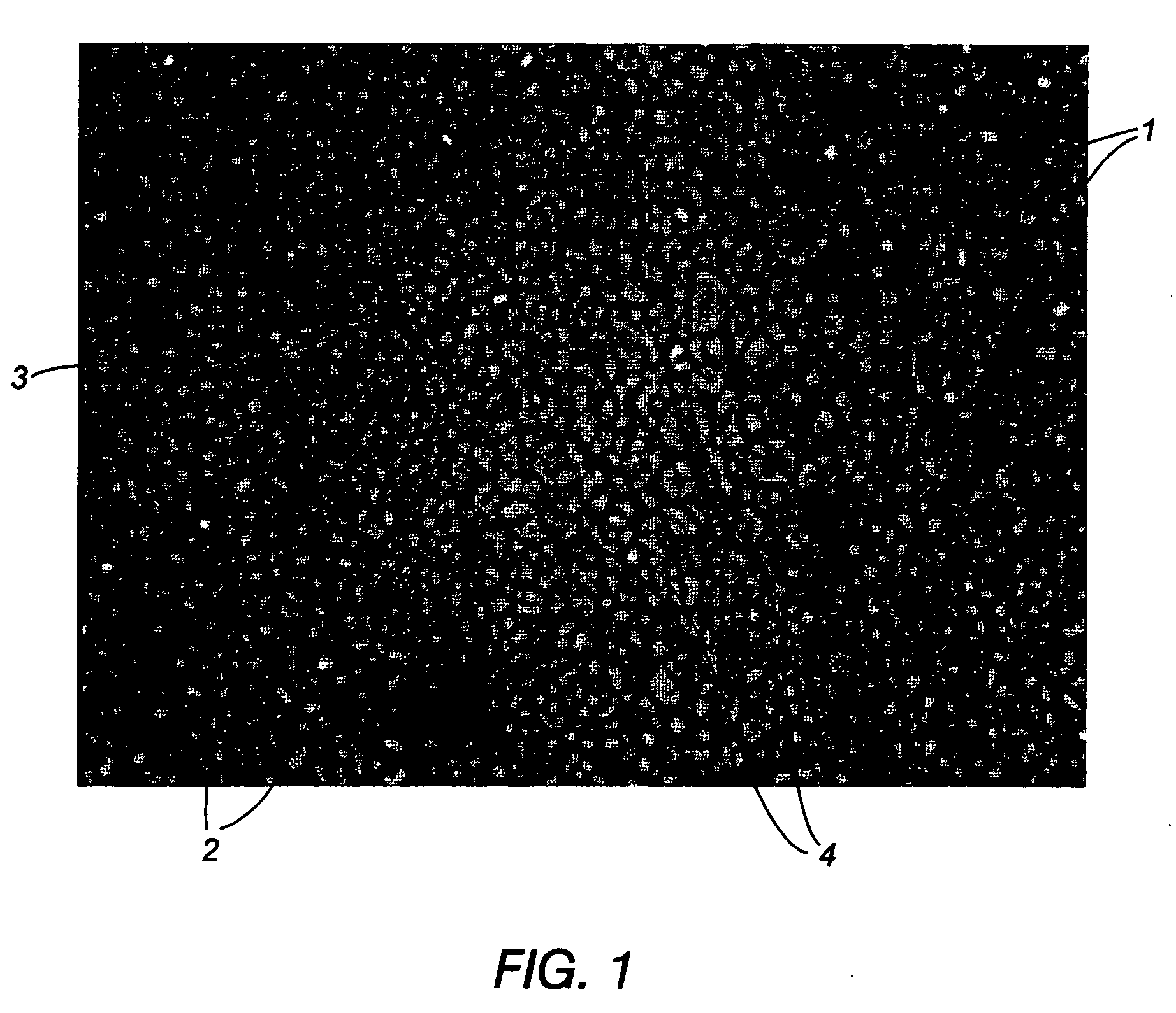
[0082] This example demonstrates that preheating the coating solution to a temperature of 70° C. prior to coating eliminates the presence of both the circular and elliptical domains that were present throughout the hydrated cross-section of a membrane prepared using a room temperature coating solution and drying of the coated film at 120° C. Example 2 further demonstrates that, provided the coating solution is preheated to about 70° C., either a standard (120°) or elevated (150° C.) drying temperature were sufficient to drive the DMAC solvent from the coated film quickly to further inhibit the hydrophilic and hydrophobic portions of the polyurethane membrane from segregating into large domains.

[0083] In particular, the invention was evaluated by performing a coating experiment where standard coating conditions (room temperature coating solution and 120° C. drying temperature of the coated film) were compared to conditions where the coatin...

example 3

Evaluation of The Inventive Membranes for Their Permeability to Glucose and H2O2

[0089] Membranes prepared under the EE condition described in Example 2 were evaluated for their ability to allow glucose and hydrogen peroxide to get through the membrane to a sensor. In particular, a series of polyurethane blends of the present invention were generated wherein the percentage of Chronothane H in a coating blend was varied. Furthermore, one of these blends (57.5% Chronothane H in coating blend) was prepared under both the EE condition and the SS condition as described in Example 2. FIG. 6 shows that the sensor output generated with a series of polyurethane blends of the present invention was dependent upon the percentage of the Chronothane H. In particular, the sensor output increased as the percentage of Chronothane H in the coating blend increased. With further reference to FIG. 6, when the percentage of Chronothane H in the coating blend was 57.5%, the sensor output was three times ...


PUM

PropertyMeasurementUnit
Temperatureaaaaaaaaaa
Structureaaaaaaaaaa

Abstract

The invention provides an implantable membrane for regulating the transport of analytes therethrough that includes a matrix including a first polymer; and a second polymer dispersed throughout the matrix, wherein the second polymer forms a network of microdomains which when hydrated are not observable using photomicroscopy at 400× magnification or less. In one aspect, the homogeneous membrane of the present invention has hydrophilic domains dispersed substantially throughout a hydrophobic matrix to provide an optimum balance between oxygen and glucose transport to an electrochemical glucose sensor.

Description

RELATED APPLICATION [0001] This application is a division of application Ser. No. 10 / 153,356 filed May 22, 2002, the disclosure of which is hereby incorporated by reference in its entirety and is made a portion of this application.FIELD OF THE INVENTION [0002] The present invention relates generally to membranes for use in combination with implantable devices for evaluating an analyte in a body fluid. More particularly, the invention relates to membranes for controlling the diffusion of glucose therethrough to a glucose sensor. BACKGROUND OF THE INVENTION [0003] A biosensor is a device that uses biological recognition properties for the selective analysis of various analytes or biomolecules. Generally, the sensor will produce a signal that is quantitatively related to the concentration of the analyte. In particular, a great deal of research has been directed toward the development of a glucose sensor that would function in vivo to monitor a patient's blood glucose level. Such a gluc...

Claims


Application Information

Patent Timeline
IPC IPC(8): B32B27/40G01N27/30A61B5/145A61B5/1473B01D69/14B01D71/54B01D71/80C12M1/40C12Q1/00C12Q1/54G01N27/28G01N27/327G01N27/416
CPCB05D3/007C12Q1/002B01D71/54B01D69/141A61B5/1473B01D71/80A61B5/14532B05D5/00Y10T428/31551A61B5/1486C12Q1/006A61L31/12A61B5/14865A61B2562/028A61B2562/125
Inventor TAPSAK, MARK A.RHODES, RATHBUN K.SHULTS, MARK C.MCCLURE, JASON D.
Owner DEXCOM
Why Eureka
Try Eureka