

High frequency electrical signal control device and sensing system
a technology of high-frequency electrical signals and control devices, applied in the direction of radiation measurement, optical radiation measurement, compasses, etc., can solve the problems of high cost of transmitters and receivers, unsuitable for mass production, and power consumption
- Summary
- Abstract
- Description
- Claims
- Application Information
AI Technical Summary
Benefits of technology
Problems solved by technology
Method used
Image

Examples
first embodiment
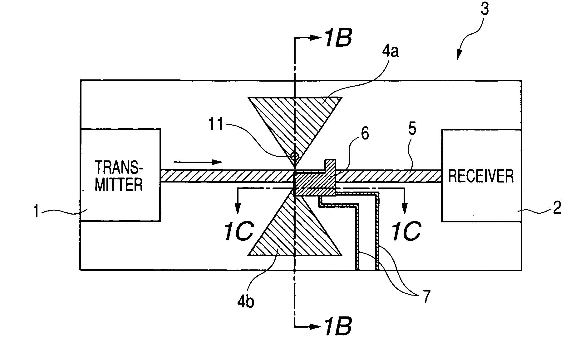
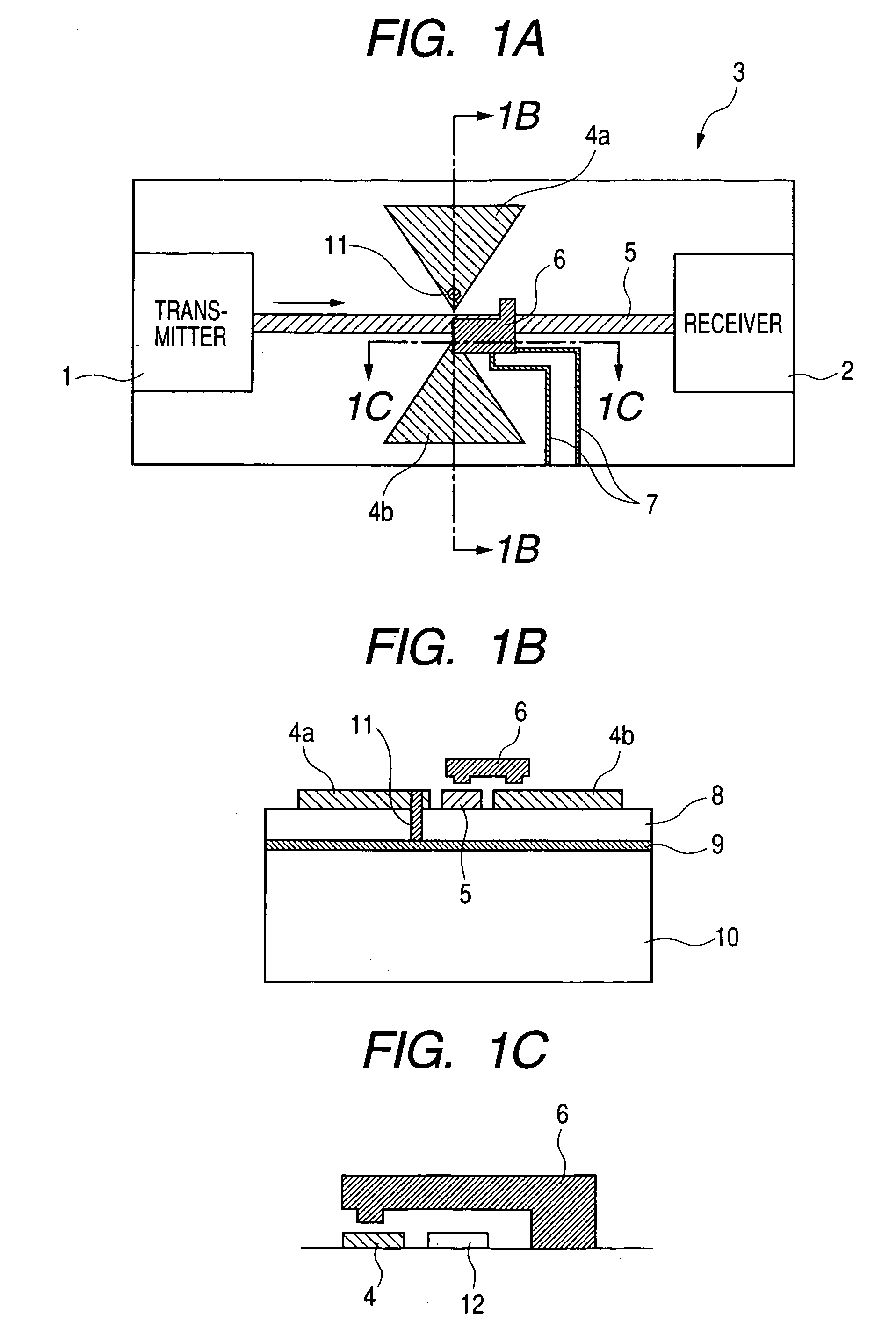
[0036] A first embodiment according to the present invention is shown in FIGS. 1A to 1C. In the first embodiment, as shown in FIG. 1A, bow tie type thin film antennas 4a and 4b are formed in the middle of a microstrip line 5 on the same module 3, and connection between the microstrip line 5 and the antennas is controlled with a miniature contact switch 6. While a transmitter 1 and a receiver 2, as shown in FIG. 1A, are integrated within the same module in a hybrid manner, there may be adopted a form in which the transmitter 1 and the receiver 2 are connected to an external transmitter or receiver. As for the transmitter, for example, an oscillation circuit for a microwave and a millimeter wave may be used in which a hetero-bipolar transistor (HBT) is used as an amplifier. A Schottky barrier diode (SBD) may be used as the high speed receiver. As shown in FIG. 1B shown as a cross sectional view taken along line 1B-1B of FIG. 1A, the microstrip line 5 is structured such that a ground p...
second embodiment
[0042] In the construction of the first embodiment, the signal control may not be carried out because the electromagnetic wave is reflected by the transmission line or the antenna depending on the frequency bands in some cases. Then, this embodiment aims at controlling flows of signals using circulators. FIGS. 4A and 4B show this embodiment in which a flow of a signal from a transmitter 1 to an antenna 23, and a flow of a signal from the antenna 23 to a receiver 2 are limited to one direction by circulators 22 and 26. The signal from the antenna 23 to the receiver 2 is a composite signal which is obtained by composing an electromagnetic wave generated through reflection of the signal from the transmitter 1 with an electromagnetic wave received from the outside. Note that a signal from the receiver 2 to the transmitter 1 is not illustrated since its magnitude is weak. This circulator, as shown in a cross sectional view of FIG. 4B, is structured by embedding a ferrite plate 26 in a ci...
third embodiment
[0044] A construction of this embodiment is shown in FIGS. 5A and 5B. In the above-mentioned embodiments, only ON / OFF control is carried out for the radiation of the electromagnetic wave from the antennas, and the magnitude of the signal supplied to the antennas when the signal is radiated in the form of an electromagnetic wave is fixed. However, in this embodiment, a horn antenna 34 manufactured so as to be miniature is moved to control a degree of signal supply in order to change the intensity of a radiated electromagnetic wave or a received electromagnetic wave.
[0045] Transmission lines 30 and 31, a transmitter 1, and a receiver 2 are the same as those in the second embodiment. In addition, while in the second embodiment, the flows of the signals are controlled using the circulators, in this embodiment, only direct propagation of a signal from the transmitter 1 to the receiver 2 is limited using a directional coupler 35 and a resistor 32. Its isolation ratio can be controlled on...
PUM
 Abstract
Description
Claims
Application Information