[0015] Although the preferred embodiment described herein is described in terms of the harshest conditions, namely the application of the inventive multi-layer wrap system to pilings used in a marine environment, and more particularly to salt-water marine construction such as docks and navigation structures, it should be understood that the various embodiments of the inventive wrap system apply equally to wrapping the bases of power and other pole structures (e.g., pole and beam building structures;
deck and building support structures; telephone, utility and light poles; fencing, barrier and support structures; grandstands; automotive and railroad trestles and ties; and the like) emplaced in soil on land in a wide variety of environments,
ranging, for example, from persistently dry to persistently or occasionally wet, including marshes, flood plains, low spots, water run off areas, streams, rivers, ponds and lakes. In the case of the marine environments, the inventive multi-layer wrap system functions to prevent
attack primarily from marine organisms, and in the case of the land emplaced environments, the inventive wrap system functions to prevent
attack primarily from insects,
fungus and rot. In both types of uses, the inventive wrap system also functions to encapsulate and reduce leaching into the environment of preservatives used in and on the pilings and poles, whether
creosote or other organic or organo-metallic compounds, paints, anti-corrosion coatings and the like.
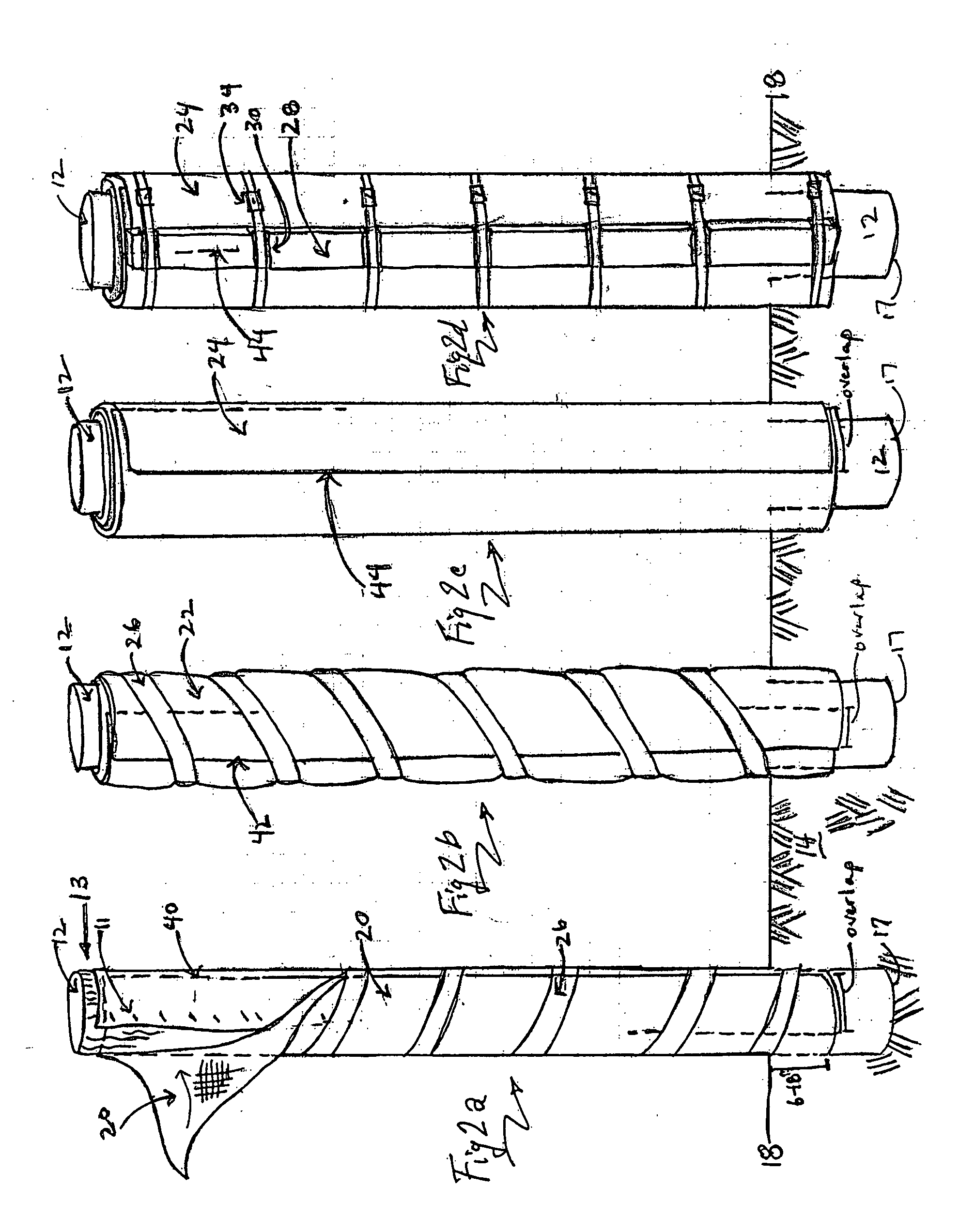
[0017] A second, wrap layer comprising a compression shell-like cover layer (called the compression layer) of relatively rigid but flexible, tough, high molecular weight
polyolefin polymer (HMWP) of thickness in the range of from about 0.040″ to about 0.150″ thickness is installed over and around the seal layer and secured in place with a vertical seal bar and
corrosion resistant strapping system, which tightly seals the layered wrap and prevents water and
oxygen from seeping in. This compression cover wrap is preferably selected from
polyethylene,
polypropylene or co-polymers of polyolefins, and preferably also includes UV stabilizer compounds to confer resistance to
polymer breakdown due to
sunlight, and
carbon black or other colorants for
weathering resistance and to confer
opacity to assist in protecting the seal wrap or the optional intermediate
gasket layer. Other additives may be used in the plastic compression layer to confer abrasion resistance, the desired degree of flexibility and
toughness, color, and the like.
[0021] In this second preferred embodiment employing a third, intermediate foam conformation /
gasket layer of the inventive piling and pole wrap system, a continuous sheet of ¼″-½″ thick, closed or open-
cell, water-resistant
plastic foam is wrapped tightly against the first seal wrap, acting as a
gasket which compresses the first layer to the piling or pole surface, to assist the first layer to conform to the grain and / or other surface irregularities, to better seal the piling surface. The flexibility and
compressibility of the closed /
open cell foam acts to fill and seal any irregularities in the surface of the piling or pole, particularly wood ones, sealing both
layers flush against the piling or pole surface. One skilled in the art can easily determine whether or not the foam gasket layer may be employed based on weather, water and use conditions, such as: the degree of typical water, mud or earth movement surrounding the piling or pole; the amount of wood
preservative in the piling or pole; the nature and texture of the piling or pole surface (smooth vs. pitted or rough); or the age or / and deterioration already sustained by the piling or pole, particularly in the case of retrofit wrapping.
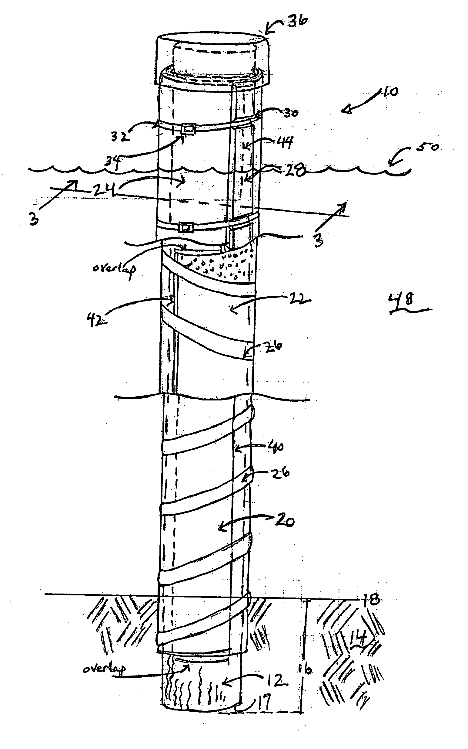
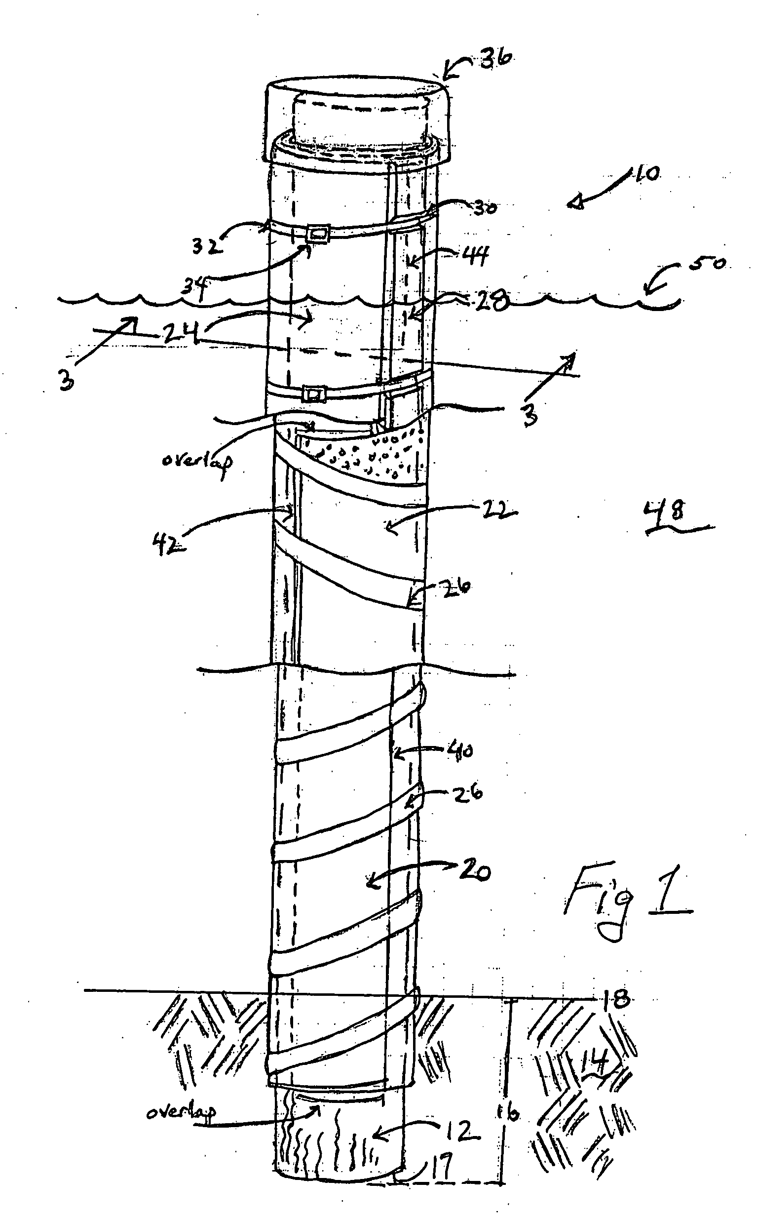
[0029] In the case of poles, it is preferred to wrap the entire base of the pole that is installed in-ground, to some 6-18″
above ground level. That is, in the case of pilings the preferred wrap is top down to some 12-24″ below the sea, river, lake or
marsh mud line, the remaining being un-wrapped, whereas in the case of poles, the wrapping is from bottom up to some 6-18″
above ground line. However, it should be understood that in the case of sensitive marine environments, whether fresh or
salt water, it may be preferred or necessary to wrap the entire section of the piling or pole emplaced in the sea, lake, river, pond or
marsh bed. To wrap the bottom of the piling or pole, that is the butt end, the inner seal layer is extended beyond the butt end of the piling or pole, and upon wrapping, the extension is folded over the butt and around the lower portion of the side-wall wrap. Then the outer compression layer shell can secure the folded material. In this case, the foam inner layer may be omitted in the area of the folded material. In addition, the folded material may be
cut off square, that is, transverse to the longitudinal axis of the piling or pole to eliminate any undesirable bunching of material. As an alternative, a plastic end cap can be secured to and over the butt, wrapped or not, and the shell layer abuts the edges of the cap to provide an integral shell that covers the butt as well as the piling or pole sides.
[0034] A fourth alternate embodiment for attaching the inventive wrap is employed for pilings or poles which have already sustained some deterioration or use damage. In this embodiment, the two or three-layer inventive wrap system is held in place with opposed, hot-dipped galvanized steel C-channels running beyond (above and below) the length of the damaged area to act as a splint to reinforce the piling. These channels can run the full length of the piling, if needed. The C-channel is affixed to the piling with
carriage through-bolts located vertically, generally every 2′ along the length of the reinforcing channels. The bolts are oriented on a
diameter of the piling and, upon tightening, place the channels in compression to reinforce the piling. In addition they assist in retaining and sealing the compression shell. If deterioration has rendered any area too soft to hold a bolt, they may be installed at irregular intervals to insure that the bolts are anchored into healthy wood or other piling or pole surface material.

