Processes and systems for formation of high voltage, anodic oxide on a valve metal anode

Inactive Publication Date: 2006-05-04
MEDTRONIC INC
View PDF14 Cites 66 Cited by
  • Summary
  • Abstract
  • Description
  • Claims
  • Application Information

AI Technical Summary

Benefits of technology

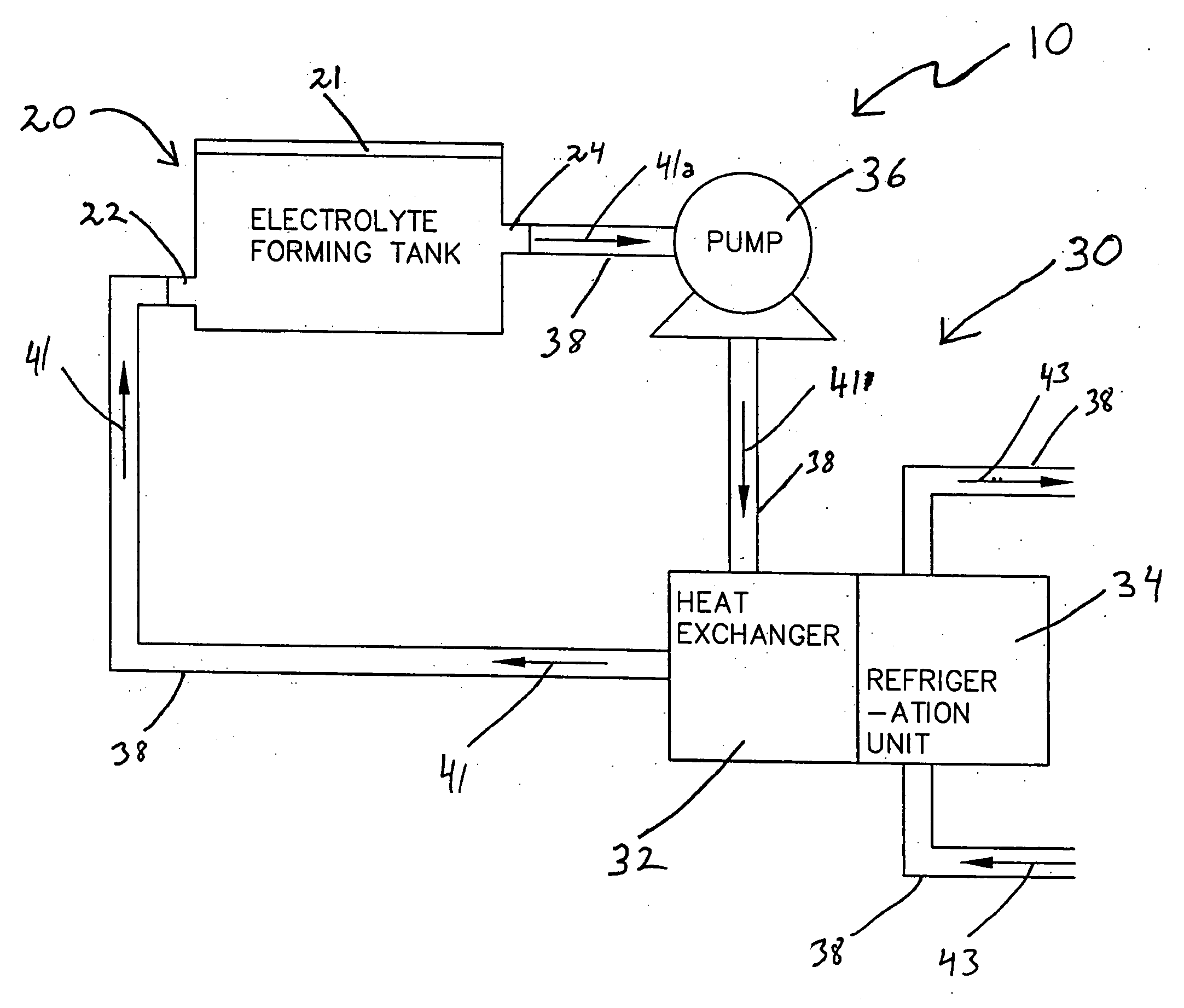
[0037] The invention is specifically useful for forming high voltage, high capacitance anodes as it allows for managing the thermal energy dissipation durin

Problems solved by technology

Earlier automatic implantable defibrillators (AIDs) did not have cardioversion or pacing capabilities.
Given the rising popularity, efficacy, declining prices and recent over-the-counter status of certain AEDs, such devices are almost certainly becoming small and more portable.
Both ICDs and AEDs have historically utilized relatively bulky and expensive battery and high voltage capacitor units to provide the energy required for the therapies they provide.
At the same time, reliability of the high-voltage capacitors cannot be compromised.
Furthermore, it is critical that electrolyte may flow fairly readily through the structure because a significant amount of electrical power may be dissipated as heat during the formation process.
The above-referenced '993 patent reports that there are problems with conventional valve metal anodization processing due to heating of the electrolyte inside the interstitial pores of the porous tantalum pellet during the anodization process.
In the hot areas of the karst-like structure, which may be likened to an assembly of steam vessels, the electrolyte may decompose and/or the sinter-structure may crack because of the increased internal pressure.
As a consequence, instabilities may be introduced into the system, which adversely affect the performance of the capacitor.
Such instabilities are, of course, unacceptable.
This method clearly can become very time consuming, as can be r

Method used


Image

  • Processes and systems for formation of high voltage, anodic oxide on a valve metal anode
  • Processes and systems for formation of high voltage, anodic oxide on a valve metal anode
  • Processes and systems for formation of high voltage, anodic oxide on a valve metal anode

Examples


example 1

[0081] A set of 8 capacitors were formed with the pulsed formation technique depicted in FIG. 8 and discussed earlier herein. Anodes 1 through 4 were processed in a system without active temperature control, which allowed the bath temperature to fluctuate or climb up to 40° C. at the time of maximum power dissipation, a traditional method. Anodes 5 through 8 were processed in a system with accurate temperature control of the formation bath, keeping the temperature constant at 18° C., a method according to the invention. Processing conditions were otherwise the same for all 8 electrodes, with the exception of the use of active temperature control according to the invention in the processing of Anodes 5-8 to accurately maintain the temperature of the formation electrolyte at 18° C. The target potential was 260 V, initial formation current was 275 mA for four anodes. Formation frequency was about 0.2 mHz with a duty cycle between 95% and 75% depending on the power dissipation. Table 1 ...


PUM

PropertyMeasurementUnit
Temperatureaaaaaaaaaa

Abstract

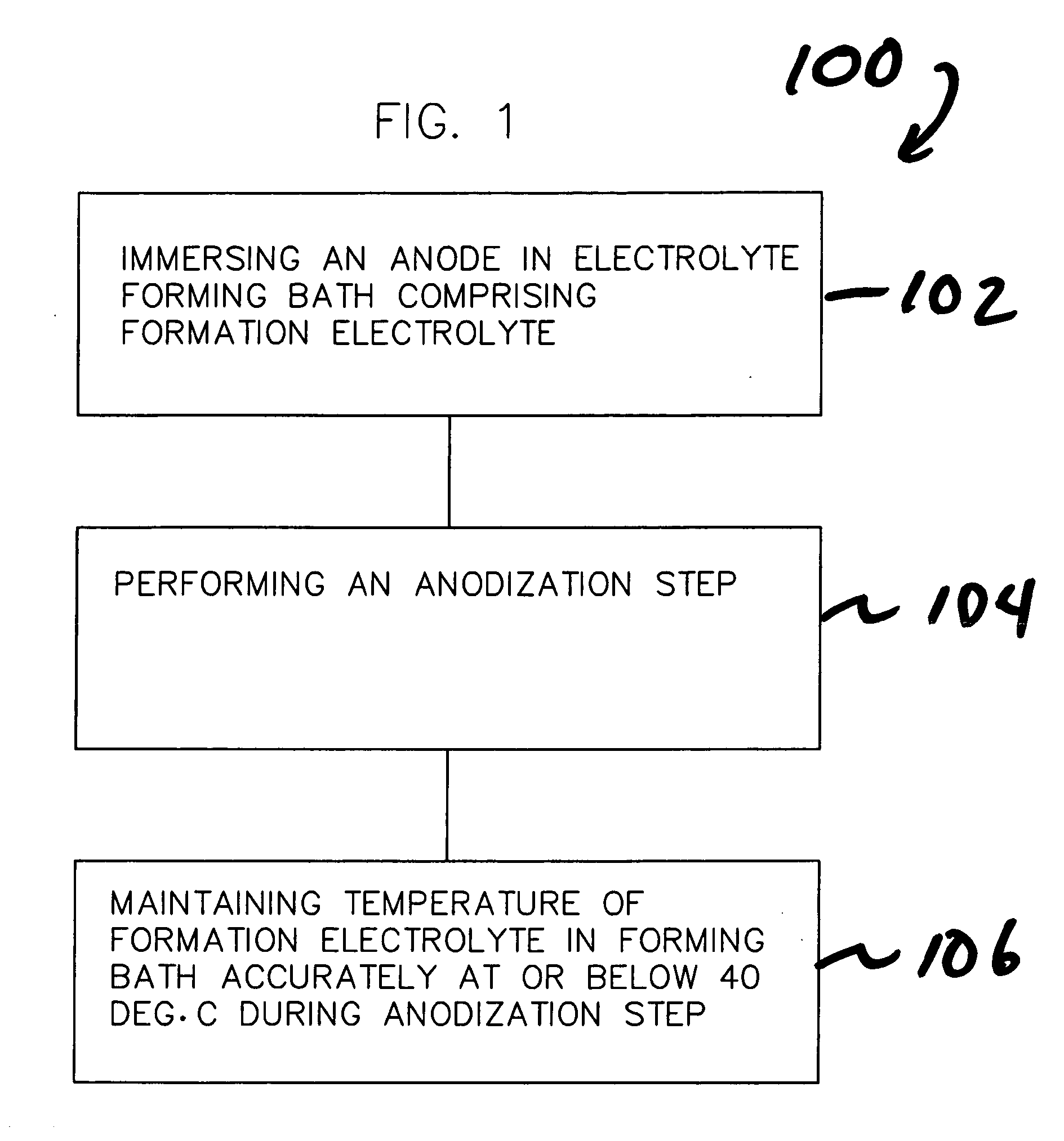
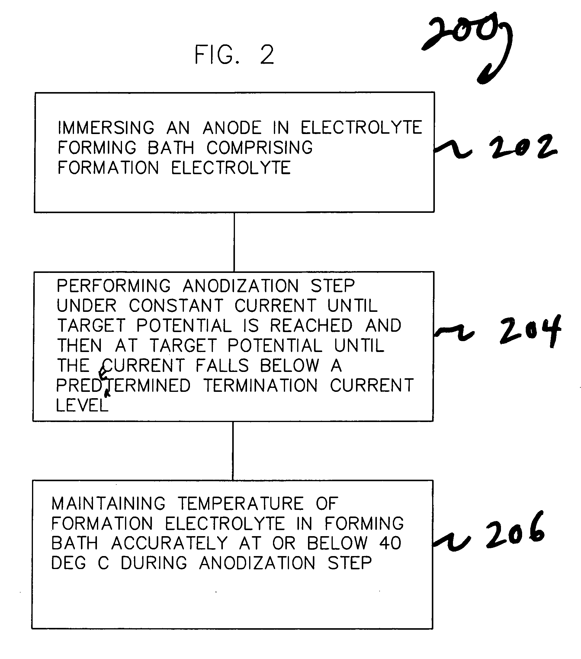
Processes and systems for formation of high voltage, anodic oxide on a valve metal anode. The processes generally includes immersing a valve metal anode in an electrolyte forming bath comprised of a formation electrolyte, performing an anodization step; and maintaining or regulating the temperature of the formation electrolyte accurately at a temperature at or below 40° C. during the anodization step. The anodization firstly under constant current until a target potential is reached and secondly under constant potential at the target potential until the current falls below a predetermined termination current level. The systems generally include a tank configured to receive one or more anodes in an electrolyte forming bath comprised of a formation electrolyte; and a subsystem for cooling and maintaining the formation electrolyte at the desire processing temperature. The systems may further include electronic controls for monitoring and adjusting system or process parameters.

Description

FIELD OF THE INVENTION [0001] This invention relates to processes and systems for forming high voltage, anodized valve metal anodes for use in wet electrolytic capacitors. This type of anode is suitable for use in high voltage capacitors particularly for use in implantable medical devices (IMDs). BACKGROUND OF THE INVENTION [0002] The term “valve metal” stands for a group of metals including aluminum, tantalum, niobium, titanium, zirconium, etc., all of which form adherent, electrically insulating, metal-oxide films upon anodic polarization in electrically conductive solution, e.g., formation electrolytes. [0003] Wet electrolytic capacitors generally consist of an anode, a cathode, a barrier or separator layer for separating the anode and cathode and an electrolyte. In tubular electrolytic capacitors, anodes are typically composed of wound anodized aluminum foil in which subsequent windings are separated by at least one separator layer. The anodes in flat electrolytic capacitors may...

Claims


Application Information

Patent Timeline
IPC IPC(8): C25D9/00C25D11/00C25D17/00
CPCC25D11/12C25D11/26H01G9/042C25D11/024C25D11/005
Inventor HOSSICK-SCHOTT, JOACHIMYOUNG, PAUL B.
Owner MEDTRONIC INC
Why Eureka
Try Eureka