Object identification structure and object provided with the same

Inactive Publication Date: 2006-05-11
NIPPON OIL CORP
View PDF16 Cites 13 Cited by
  • Summary
  • Abstract
  • Description
  • Claims
  • Application Information

AI Technical Summary

Benefits of technology

[0047] A single layer cholesteric liquid crystal film is formed on an alignment substrate using the above-described film materials. Examples of the alignment substrate include glass sheets, plastic film substrates, plastic sheets and polarizing films. Examples of the glass sheets include sodalime glass, alkali glass, alkali-free glass, borosilicate glass, flint glass and quarts glass. Examples of the plastic film substrate include polymethyl methacrylate, polystyrene, polycarbonate, polyether sulfone, polyphenylene sulfide, amorphous polyolefin, triacetyl cellulose, polyethylene terephthalate, and polyethylene naphthalate.
[0048] An alignment film to be applied on a substrate is preferably a polyimide film having been subjected to a rubbing treatment but may also be any alignment film known to the relevant fields. In the present invention, any plastic film or sheet directly provided with alignability by a rubbing treatment without coating thereon such a polyimide film may be used as the alignment substrate. There is no particular restriction on the aligning treatment as long as the molecules in the cholesteric liquid crystal layer can be equally aligned parallel to the rubbed surface of each layer.
[0049] On a rubbed surface of or an alignment film on a substrate is formed a chole

Problems solved by technology

However, it is much more difficult to duplicate the liquid crystal film of the present invention because the optical characteristics thereof is determined by the three-dimensional spacing of

Method used


Image

  • Object identification structure and object provided with the same
  • Object identification structure and object provided with the same
  • Object identification structure and object provided with the same

Examples


example 1

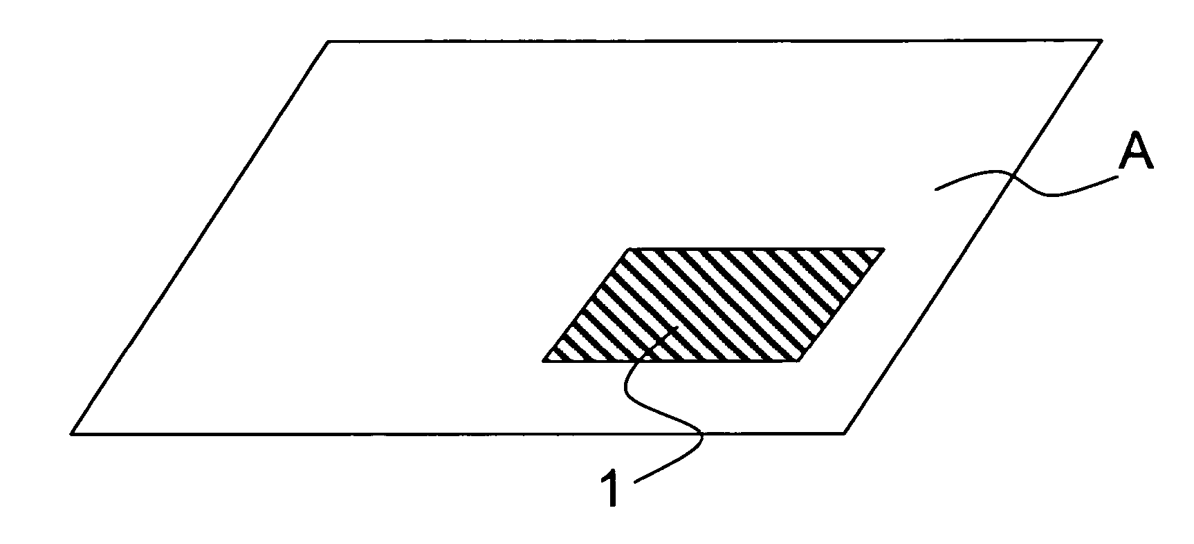
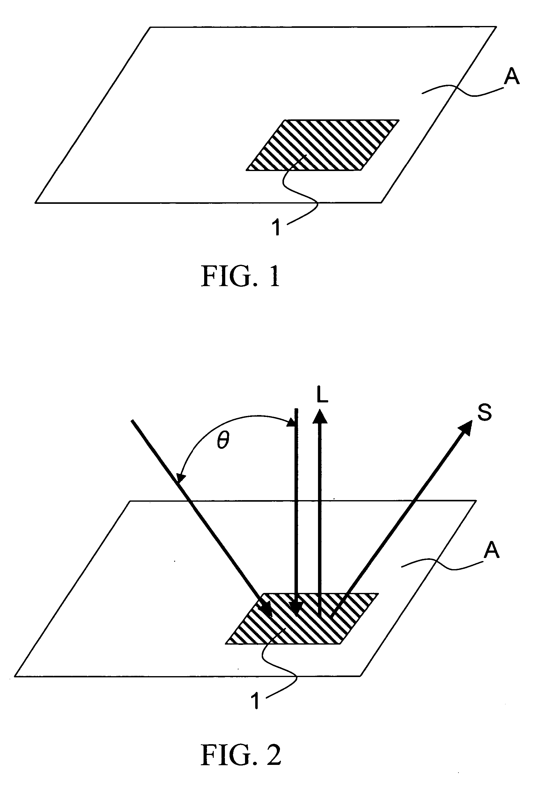
[0066] Referring to FIG. 2, a foil formed from a single layer cholesteric liquid crystal film according to the present invention serving as an identification medium is transferred or attached to a suitable location on a surface of an object A.

[0067] When a random light is irradiated to the assembly, a light with a certain color corresponding to the characteristics of the liquid crystal is reflected therefrom. The authenticity of the object can be verified by visually or mechanically detecting the reflected light. Because a similar effect may be obtained even by applying or printing a normal ink, it is preferable to increase gradually the incident angle θ of the light with respect to the normal axis to the liquid crystal surface and verifying through the change in color. As described above, the wavelengths of the reflected lights which reinforce or amplify each other continuously change to the short wavelength side, and thus the reflected light changes in color thereby improving the...

example 2

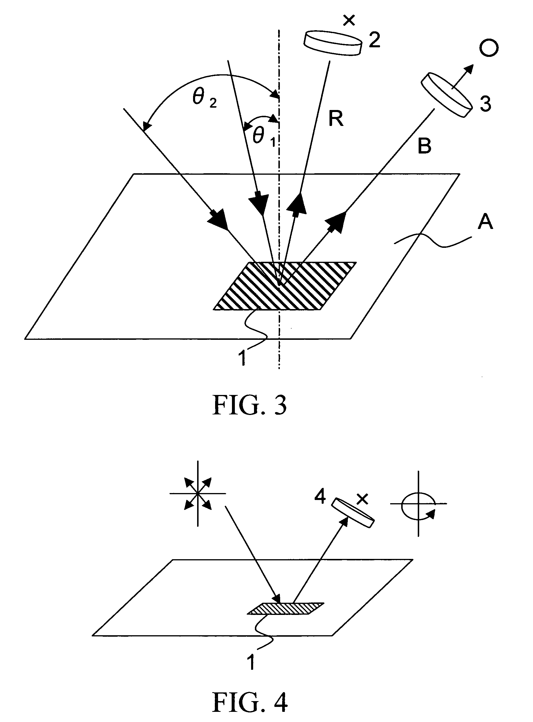
[0068] Referring to FIG. 3, in this example, a foil 1 formed from a cholesteric liquid crystal film serving as an identification medium is transferred or attached to a suitable location on a surface of an object A. Furthermore, a filter 2 shutting off the light of the reflection wavelength of the liquid crystal is placed in the path of the reflected light of a light made incident at an angle of θ1 with respect to the normal axis to the foil 1, and a similar filter 3 is placed in the path of the reflected light of a light made incident at an angle of θ2 with respect to the normal axis to the foil 1.

[0069] When a random light is made incident at the angle of θ1 onto the foil 1 and the liquid crystal has the characteristics to reflect red light, the reflected light does not pass through the filter 2 thereby producing a dark view therethrough and thus the reflected light is not recognizable. When a random light is made incident at the angle of θ2, the wavelengths reinforcing or amplify...

example 3

[0070] Referring to FIG. 4, in this example, a foil 1 formed from a cholesteric liquid crystal film serving as an identification medium is transferred or attached to a suitable location on a surface of an object A. A liquid crystal filter 4 containing a cholesteric liquid crystal film having the characteristics to reflect only a circularly polarized light component whose polarizing direction (right or left) and wavelength are the same as those of the light reflected by the foil 1 is located in a path of light reflected by the foil 1.

[0071] When a random light is irradiated on the foil 1, the reflected light does not pass through the filter 4 thereby producing a dark view therethrough and thus the reflected light is not recognizable. However, when the object is viewed without through the filter 4, a reflected light of a predetermined color can be recognized. The authenticity of the object may be verified by visually recognizing this difference. Alternatively, the authenticity may be...


PUM


Abstract

An object identification structure for generally distributed products is provided which is extremely hard to forge, high in identifiability, and can be manufactured inexpensively. The object identification structure comprises a single layer cholesteric liquid crystal film which is substantially colorless and transparent when viewed from the front and appears colored when viewed from a predetermined oblique direction.

Description

CROSS-REFERENCE TO RELATED APPLICATIONS [0001] This application is a continuation of International Application No. PCT / JP2004 / 009512, filed Jun. 29, 2004, which was published in the Japanese language on Jan. 13, 2005, under International Publication No. WO 2005 / 002874 A1, and the disclosure of which is incorporated herein by reference.BACKGROUND OF THE INVENTION [0002] The present invention relates to identification structures for preventing forgery of various two-dimensional and three-dimensional objects or articles such as passports, cards, security notes, gift certificates, pictures, public transportation tickets, public betting tickets, and various commercial goods, and in particular to identification structures for verifying the authenticity of such objects by visually or mechanically recognizing an identification (security) medium attached thereto. [0003] It has been conventionally practiced to prevent the forgery of an object such as a card and a security note by visually ide...

Claims


Application Information

Patent Timeline
IPC IPC(8): B42D15/00B42D15/10G02B5/30
CPCB42D2033/26B42D25/00B42D2035/24B42D25/30G06K7/10G06K19/06G06K19/16B42D25/364
Inventor NISHIMURA, SUZUSHISEKI, TAKASHIIMAFUKU, HIROSHI
Owner NIPPON OIL CORP
Why Eureka
Try Eureka