Liquid phase diffusion welding method for metallic machine part and metallic machine part

a liquid phase diffusion welding and metallic machine technology, applied in non-electric welding apparatus, machines/engines, cams, etc., can solve the problems of limited reduction of alloy foil thickness, and limited diffusion of isothermal solidification, so as to improve the quality of the joint, improve the tensile strength, and reduce the effect of welding tim

Active Publication Date: 2006-07-27
NIPPON STEEL CORP +1
View PDF9 Cites 14 Cited by
  • Summary
  • Abstract
  • Description
  • Claims
  • Application Information

AI Technical Summary

Benefits of technology

[0019] The present invention considers the problems harbored by the above prior art and has as its object the provision of a liquid phase diffusion bonding method for a metal machine part enabling the bonding time to be shortened compared with the conventional liquid phase diffusion bonding method, achieving homogenization of the bonding structure and improvement of the tensile strength, fatigue strength, and other aspects of joint quality and reliability compared with the conventional resistance welding methods, and superior in the quality of the joint and the productivity and of a metal machine part assembled using the same.

Problems solved by technology

Further, the bonding is completed in a relatively short time.
However, the liquid phase diffusion bonding disclosed in these patent publications enables the bonding time to be made a relatively short time, but the isothermal solidification proceeds limited by diffusion.
By making the amorphous alloy foil used for the liquid phase diffusion bonding thinner, the bonding time can be shortened to a certain extent, but the effect of the precision of working of the bevel faces of the bonded materials on bonding defects and the deterioration of the joint strength becomes greater, so there are also limits to the reduction in thickness of the alloy foil.
Further, even if raising the pressing stress in liquid phase diffusion bonding, while it is possible to shorten the bonding time to a certain extent, raising the pressing stress makes the bonded materials more susceptible to buckling deformation, so there are limits to increasing the pressing stress.
Accordingly, in the methods for producing metal machine parts using liquid phase diffusion bonding disclosed in Japanese Unexamined Patent Publication (Kokai) No. 2003-181651 and Japanese Unexamined Patent Publication (Kokai) No. 2001-321963, improving the productivity of the metal machine parts and reducing the production costs by shortening the bonding time while maintaining the joint quality in liquid phase diffusion bonding has become an issue in the industry.
However, when using these resistance welding methods to produce metal machine parts, sometimes fluctuations in the bonding conditions will cause for example bonding defects due to residual oxide-based inclusions at the bonds or insufficient welding current will cause so-called “cold welding” or welding defects due to insufficient melting.
Further, the pressing at the time of bonding causes large deformation to occur, fine cracks occur at the welded parts, and the bevel ends remain unbonded, which become causes of a reduction in joint performance, particularly fatigue strength.
As measures against this, in the past, for example, changes in the material design or post-processing for improving the shape of the weld was required and there were problems such as the limitations on the freedom of the joint design, increase of costs, etc.
In addition to this, in resistance welding, sometimes the weld width is extremely narrow and bevel deformation occurs, so quality assurance by nondestructive testing was difficult.
Due to this and other reasons, improvement of the bonding quality in resistance welding in bonding joints where reliability is particularly required is an issue in industrial technology.
That is, no isothermal solidification diffusion treatment is being performed to convert the incomplete isothermal solidification structures of the resistance welds occurring in primary bonding in the methods disclosed in the above patent publications to liquid phase diffusion bonding structures, so it is difficult to sufficient raise the quality of the bonds.
Of course, ordinary welding can be used for iron base materials and use of ordinary welding technology is difficult for bonding heterogeneous joints.

Method used


Image

  • Liquid phase diffusion welding method for metallic machine part and metallic machine part
  • Liquid phase diffusion welding method for metallic machine part and metallic machine part
  • Liquid phase diffusion welding method for metallic machine part and metallic machine part

Examples


example 1

[0093] Amorphous alloy foils for liquid phase diffusion bonding having the three types of chemical compositions of the symbols A to C and melting points shown in Table 1 and bonded materials comprised of ferrous metals, Ni alloys, or Ti alloys having the chemical compositions of the symbols a to f shown in Table 2 were used to produce metal machine parts under the bonding conditions shown in Table 3 and Table 4.

[0094] The metal machine parts obtained were subjected to tensile tests in the direction pulling away from the bonded surfaces and charpy impact tests of the bonds at 0° C. and were evaluated for joint strength and joint toughness. Further, the amounts of deformation of the metal machine parts in the direction of application of bonding stress were measured and the amounts of deformation evaluated. The results are shown in Table 3 and Table 4.

[0095] Note that in Table 3 and Table 4, the evaluation of the joint strength is shown by the ratio of the tensile strength of the bon...

example 2

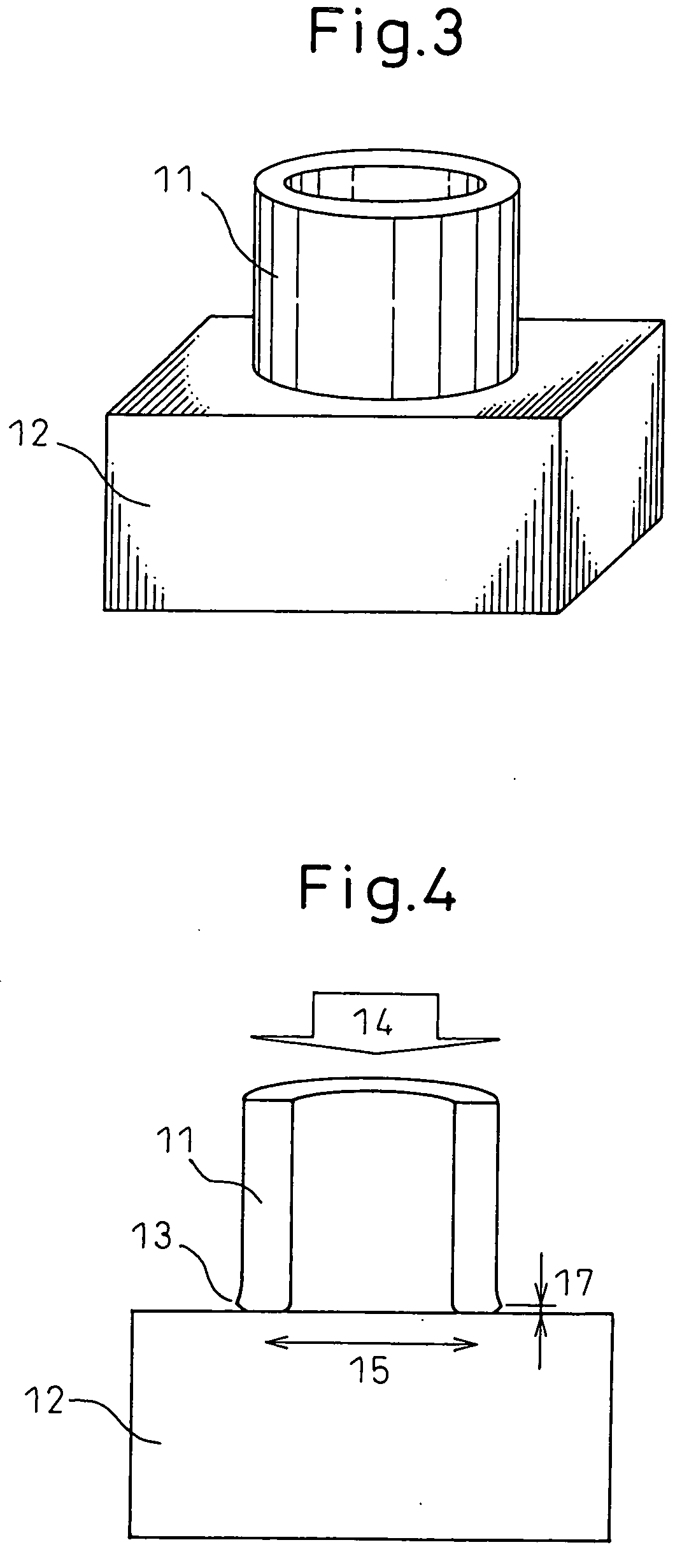
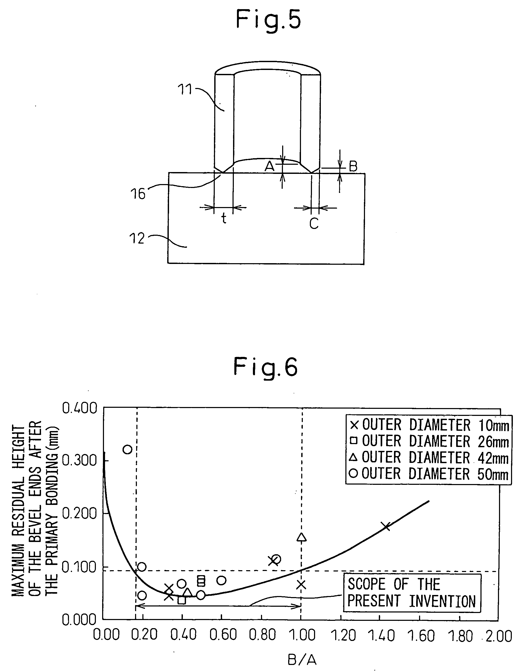
[0108] Next, the same procedure as in the invention examples of Nos. 2 to 8 shown in Table 3 of Example 1 was followed to bond branch pipes 2 and pipe bodies 1 shown in FIG. 8. At that time, as shown in Table 5, Table 6, and Table 7, metal machine parts bonded under conditions changing the dimensions of the thickness t etc. of the branch pipes 2 of the cylindrical metal materials and the bevel conditions of the branch pipes 2 (inner surface bevel height A, outer surface bevel height B, and distance C from abutting contact point to outer circumference) at the time of abutting were produced and were measured and evaluated for joint mechanical properties, in particular the fatigue strengths. Note that the chemical compositions of the amorphous alloy foils for liquid phase diffusion bonding and bonded materials used were the same as in Example 1. Further, the same procedure as in Example 1 was used for production except for the bonding conditions shown in Tables 5 and 6.

[0109] The meta...

example 3

[0121] Next, an explanation will be given of an example of application of the bonding method of the present invention when producing hollow metal machine parts such as various types of motor cam shafts fabricated conventionally by casting, forging and cutting, etc. as shown in FIG. 9.

[0122] Liquid phase diffusion amorphous alloy foils having two types of chemical compositions of the symbols A and B and melting points shown in Table 1 and bonded materials comprised of ferrous metals having the chemical compositions of the symbols “a” and “b” shown in Table 2 were used to produce metal machine parts shown in FIG. 9 by the following procedure under the bonding conditions shown in Table 8.

[0123] That is, as shown in FIG. 9, the end of a hollow metal material 18 forming one bonding face was machined in advance to give a V-bevel having an angle of 45°. The bonding faces of the bevel 19 of the hollow metal material 18 and the metal material 20 were made to abut against each other through...


PUM

PropertyMeasurementUnit
holding timeaaaaaaaaaa
timeaaaaaaaaaa
grain sizeaaaaaaaaaa

Abstract

A liquid phase diffusion bonding method for a metal machine part superior in the quality of the joint and the productivity enabling the bonding time to be shortened, achieving homogenization of the bonding structure and improving the tensile strength, fatigue strength, and joint quality and reliability. This liquid phase diffusion bonding method of a metal machine part is characterized interposing an amorphous alloy foil for liquid phase diffusion bonding at bevel faces of metal materials, performing primary bonding by melt bonding said amorphous alloy foil and said metal material by resistance welding to form a joint, then performing secondary bonding by liquid phase diffusion bonding by reheating said joint to at least the melting point of said amorphous alloy foil, then holding it there to complete the solidification process of said joint.

Description

TECHNICAL FIELD [0001] The present invention relates to a method of production of a metal machine part and to such a metal machine part, more particularly relates to liquid phase diffusion bonding method of a metal machine part used for an auto part etc. and to such a metal machine part. BACKGROUND ART [0002] In the past, as the methods of bonding metal materials with each other, welding methods had mainly been used. In recent years, however, use of the liquid phase diffusion bonding method as new industrial bonding technology for replacing this has been spreading. [0003] The liquid phase diffusion bonding method is the technology of interposing between bonding faces of bonded materials, that is, the bevel faces, an amorphous alloy foil with a melting point lower than the bonded materials, specifically a multimetal alloy foil having at least 50% of its crystal structure amorphous, containing an element having the ability to form a bonded joint through a diffusion-limited isothermal ...

Claims


Application Information

Patent Timeline
Patent Type & Authority Applications(United States)
IPC IPC(8): A47J36/02B23K11/00B23K20/00B23K20/02B23K20/16B23K20/227B23K20/24
CPCB23K11/0033Y10T428/12944B23K20/16B23K20/22B23K20/227B23K20/24B23K28/02B23K2201/005B23K2201/006B23K2201/04B23K2201/06B23K2203/04C22C14/00C22C19/03C22C19/058C22C38/001C22C38/02C22C38/12C22C38/22F01L1/047F01L2101/00F01L2103/00Y10T428/12951Y10T428/12493B23K20/023B23K2101/005B23K2101/006B23K2101/04B23K2101/06B23K2103/04F01L2301/00F01L2303/00B23K11/241
Inventor HASEGAWA, YASUSHIHONMA, RYUICHITAKAGI, YUTAKA
Owner NIPPON STEEL CORP
Why Eureka
Try Eureka