Methods and apparatus for porous membrane electrospray and multiplexed coupling of microfluidic systems with mass spectrometry

a technology of microfluidic systems and porous membranes, applied in the direction of dispersed particle separation, instruments, separation processes, etc., can solve the problems of reducing the surface area of the microchannel, the difficulty of forming high density electrospray tip arrays, and the inability to consistently establish well defined, stable taylor cones at the microchannel exit, etc., to achieve high surface area, reduce pressure, and reduce pressure

Inactive Publication Date: 2006-08-31
DEVOE DONALD L +3
View PDF0 Cites 87 Cited by
  • Summary
  • Abstract
  • Description
  • Claims
  • Application Information

AI Technical Summary

Benefits of technology

[0013] In another aspect of the invention, multiple electrospray tips may be formed in a single microfluidic substrate, with one or more microchannels used to deliver liquid to each of the tips. By using a hydrophobic porous polymer to constrain lateral dispersion of liquid at the exposed face of the membrane, spacing between adjacent tips may be as small as the diameter of the Taylor cones formed during the electrospray process, enabling dense arrays of electrospray tips to be formed with negligible contamination of analyte molecules between the tips.
[0016] In another aspect, the porous exit surface of the membrane serves as a dense array of nanoscale electrospray tips, enabling the generation of stable electrospray at low bulk fluid flow rates.
[0017] According to another aspect, the highly porous membrane reduces the pressure required to achieve sufficient liquid flow for stable electrospray when compared to pulled-silica nanospray tips.
[0018] According to another aspect, the porous membrane reduces the pressure required to achieve sufficient liquid flow for stable electrospray when compared to pulled-silica nanospray tips.
[0019] Another aspect of the invention is the ability to selectively bind molecules to the membrane surface, for example through hydrophobic-hydrophobic interactions, thereby enabling controlled interactions between the bound molecules and analyte molecules passing through the membrane during the electrospray process. The high surface area of the membrane may serve to enhance the kinetics of the molecular interactions. For example, a proteolytic enzyme such as trypsin may be bound to the membrane through hydrophobic interactions, and used to digest proteins passing through the membrane in real-time, while electrospraying the resulting protein digest. Other molecular species chosen to interact with the analyte may similarly be bound to the membrane. For example, a phosphotase may be bound to the membrane to enable the removal of phosphorylated groups from analyte proteins during electrospray.

Problems solved by technology

Although these techniques have shown excellent electrospray performance, they are not fully integrated with the microfluidic channels and thus suffer from large dead volumes which can lead to broadening of separation bands, and difficulty with fabricating high density electrospray tip arrays.
While straightforward, this approach leads to difficulty in consistently establishing well defined, stable Taylor cones at the microchannel exit due to liquid spreading, even for hydrophobic surfaces such as glass.
In addition to increasing Taylor cone volume, liquid spreading at the exit also limits the ability to realize tightly spaced arrays of multiple ESI tips, since crosstalk between adjacent channels poses a significant problem.
In general, shaped tips have been shown to significantly reduce or eliminate liquid spreading and provide very good spray stability, but are relatively difficult to fabricate, requiring additional fabrication steps including mechanical machining of the substrate or the use of additional lithographically-patterned material layers in the microfluidic system.
The latter approach has been shown to limit liquid spreading and assist in maintaining relatively small Taylor cone volumes, but does not prevent drift in the position of the Taylor cone away from the channel exit (T. C. Rohner, J. S. Rossier, H. H. Girault, Anal. Chem. 2001, 73, 5353-5357).
In addition, for the case of thin film hydrophobic coatings, damage to the coating during the electrospray process can occur.
However, the longevity of CF4 plasma surface modifications can be limited, and the processing costs are significant.
For example, the time scales for biomolecular separations and MS data acquisition are often incompatible.
Another important demand for off-line analysis arises from the need for coupling multiple parallel (multiplexed) microchannels to mass spectrometry, in which simultaneous ESI-MS from each separation channel is not feasible due to physical constraints.
Liquid-phase deposition methods including dried-droplet, fast solvent evaporation, sandwich, and two-layer preparation tend to suffer from poor homogeneity of crystallized sample, since matrix and analyte tend to partition during the solvent evaporation process, resulting in significant variations in mass resolution, intensity, and selectivity, and preventing meaningful quantitative analysis.

Method used


Image

  • Methods and apparatus for porous membrane electrospray and multiplexed coupling of microfluidic systems with mass spectrometry
  • Methods and apparatus for porous membrane electrospray and multiplexed coupling of microfluidic systems with mass spectrometry
  • Methods and apparatus for porous membrane electrospray and multiplexed coupling of microfluidic systems with mass spectrometry

Examples


Embodiment Construction

[0026] I. Apparatus

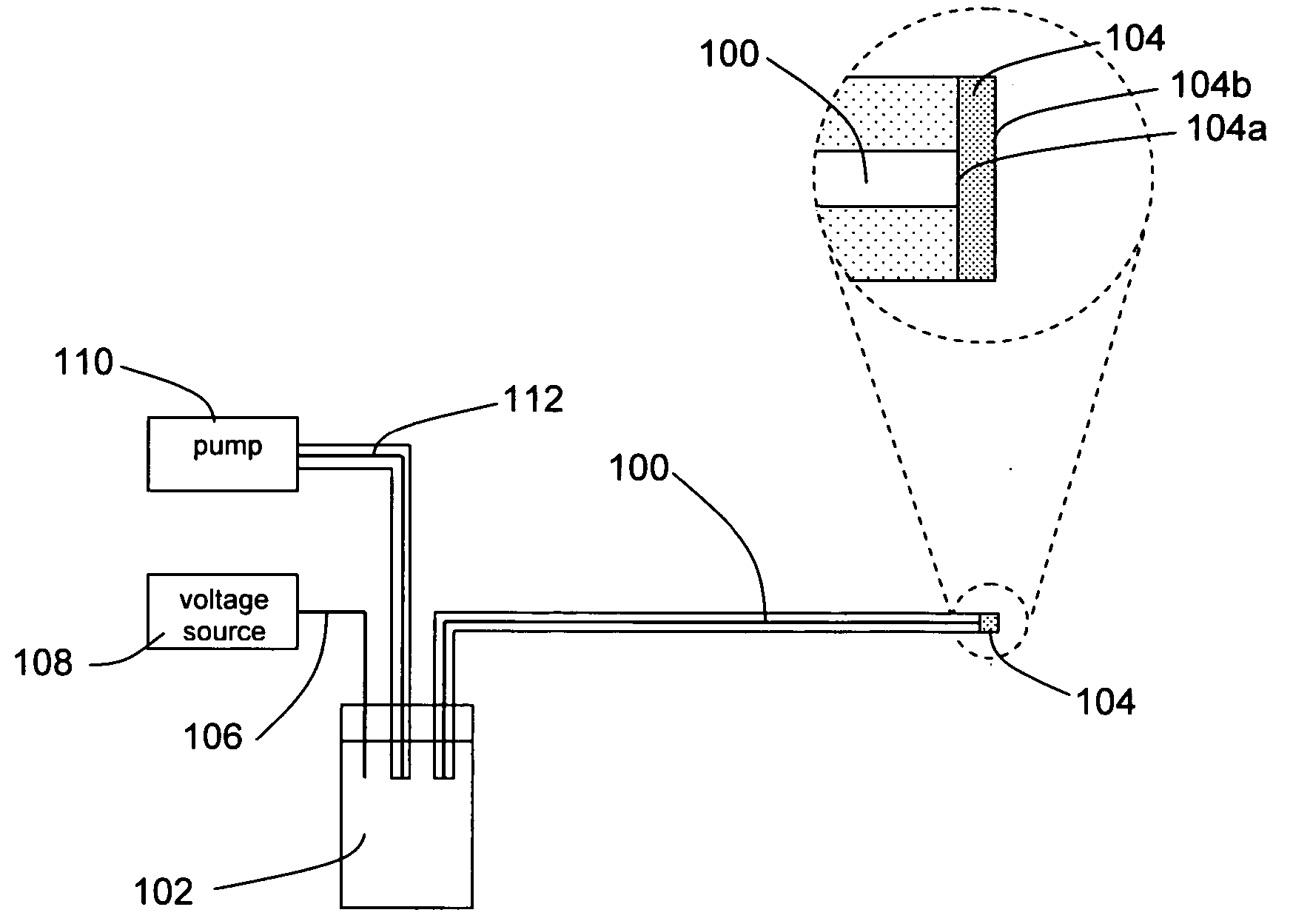
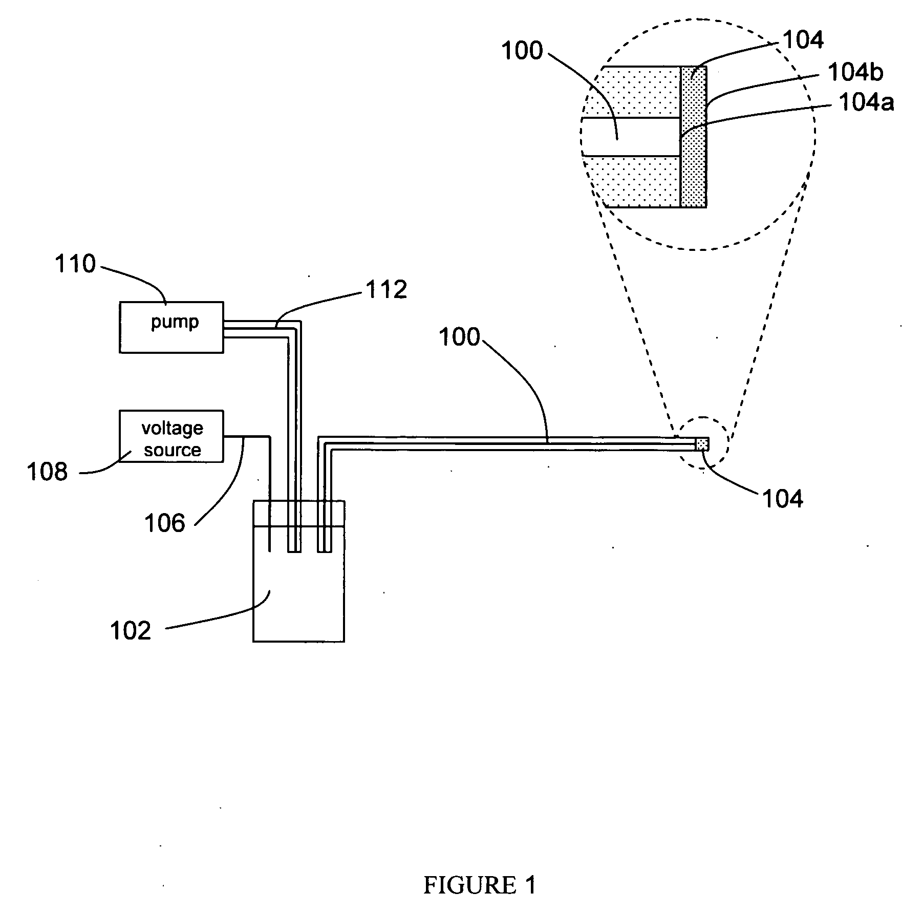
[0027] A preferred embodiment of the apparatus is depicted in FIG. 1. The apparatus comprises an electrospray microchannel 100, said electrospray microchannel possessing a first end and a second end, wherein the first end is in fluid communication with an electrospray reservoir 102, and a porous membrane 104 is affixed to the second end. The porous membrane, which possesses a bonded face 104a which is affixed to the second end of the electrospray microchannel such that the inner diameter of the electrospray microchannel is fully covered by the membrane, and an exposed face 104b which is opposite the bonded face. The membrane is bonded to the electrospray microchannel using one of several possible methods, such as thermal bonding, adhesive bonding, or solvent bonding. The apparatus further comprises an electrospray electrode 106, possessing a first end and a second end, wherein the first end of said electrode is in electrical communication with the fluid within th...


PUM


Abstract

Disclosed are an apparatus, system, and method for performing electrospray of biomolecules, particularly peptides, polypeptides, and proteins. The apparatus comprises at least (1) a microfluidic substrate for containing an electrospray microchannel for delivering analyte molecules to a side edge of the substrate, and (2) a porous membrane attached to the side edge for performing electrospray from the exposed membrane surface. In one preferred embodiment, the exposed membrane surface is positioned above a target surface for depositing analyte molecules onto the target surface by electrospray. In another preferred embodiment, a proteolytic enzyme is bound to the porous membrane for performing protein digestion during electrospray.

Description

CROSS-REFERENCE TO RELATED APPLICATIONS [0001] This application claims priority from U.S. Provisional Patent Application Ser. No. 60 / 616,525, filed Oct. 7, 2004, which is incorporated herein by reference in its entirety.[0002] This invention was made in part with government support under Grants No. R43 EB000453 and GM62738 from the National Institutes of Health, and Contract No. W911SR-04-C-0014 from the U.S. Army. Accordingly, the U.S. government may have certain rights to this invention.BACKGROUND [0003] 1. Field of Invention [0004] The invention relates to devices and methods for performing electrospray from capillary or planar microfluidic systems. The invention further relates to devices and methods for interfacing microfluidic systems with mass spectrometry. The device includes at least a reservoir, an electrode, a microchannel possessing a first end and a second end, and a porous membrane attached to the second end of the microchannel. [0005] 2. Background of the Invention [0...

Claims


Application Information

Patent Timeline
Patent Type & Authority Applications(United States)
IPC IPC(8): B01D59/44
CPCB05B5/025G01N27/44717G01N30/7266
Inventor DEVOE, DONALD L.WANG, YINGXINLEE, CHENG S.LI, YAN
Owner DEVOE DONALD L
Why Eureka
Try Eureka