

Oxynitride phosphor and light-emitting device
a technology of oxynitride and phosphor, which is applied in the field ofsilicon oxynitride fluorescent materials, can solve problems such as luminance drops, and achieve the effects of reducing luminance drops, reducing deterioration, and reducing luminance drops
- Summary
- Abstract
- Description
- Claims
- Application Information
AI Technical Summary
Benefits of technology
Problems solved by technology
Method used
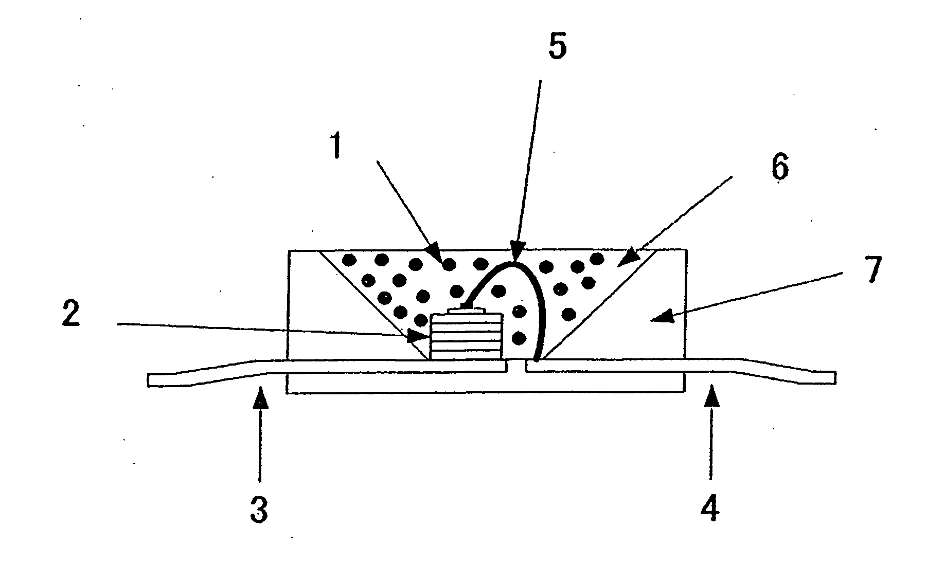
Image

Examples
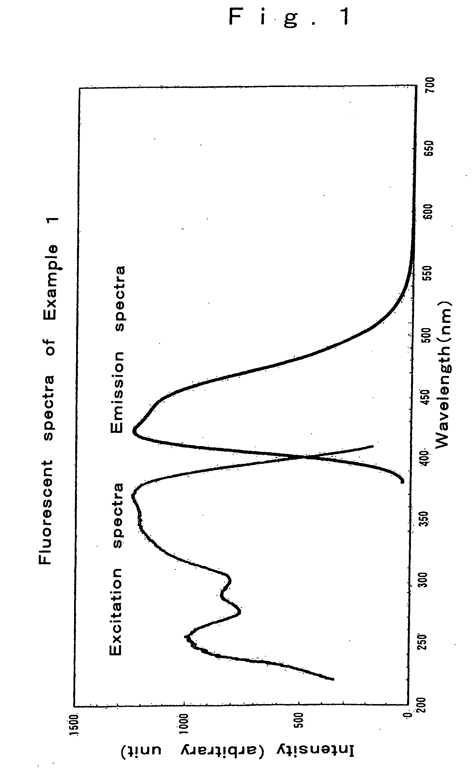
example 1
[0079] The starting powders used were silicon nitride powders having an average particle diameter of 0.5 μm, an oxygen content of 0.93% by weight and α-type content of 92%, lanthanum oxide powders with a 99.9% purity and cerium oxide powders with a 99.9% purity.
[0080] The silicon nitride, lanthanum oxide and cerium oxide powders were weighed in the respective amounts of 46.01% by weight, 43.27% by weight and 10.72% by weight so as to obtain a compound having a compositional formula Ce0.57La2.43Si9N12O4.5 (with mixture compositions of the starting powders shown in Table 1 and compositional parameters shown in Table 2). Then, the powders were mixed together with the addition of hexane in a ball mill for 2 hours, followed by drying in a rotary evaporator. The ensuring compound was molded in a mold with the application of a pressure of 20 MPa to obtain a compact of 12 mm in diameter and 5 mm in thickness.
[0081] That compact was placed in a boron nitride crucible, which was then set in...
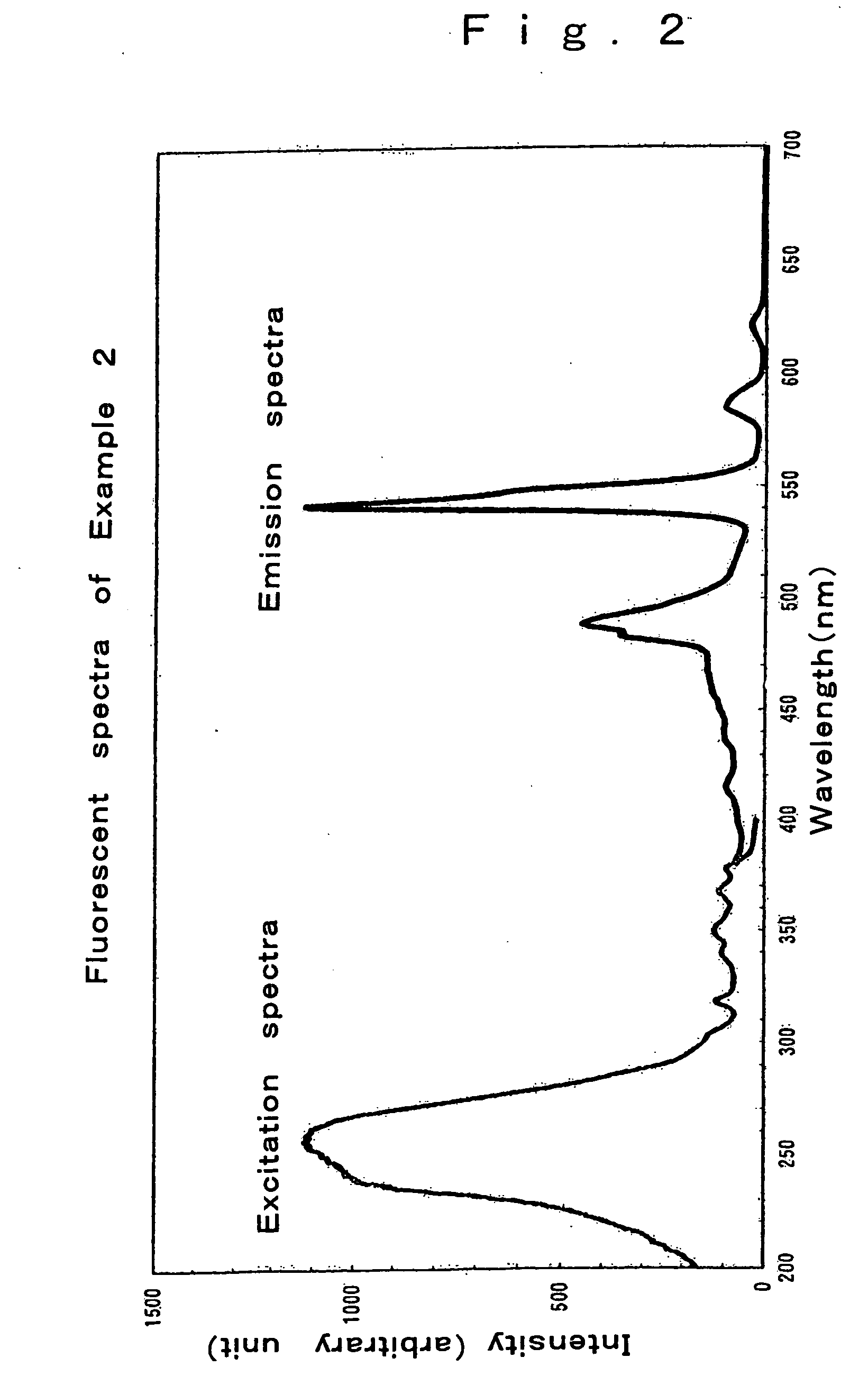
examples 2-10
[0084] The starting powders used herein were the same silicon nitride powders, lanthanum oxide powders and cerium nitride powders as in Example 1 as well as europium oxide powders with a 99.9% purity, terbium oxide powders with a 99.9% purity, aluminum oxide powders with a 99.9% purity and lanthanum oxide powders with a 99.9% purity oxynitride powders were prepared following Example 1 with the exception that the compositions set out in Tables 1 and 2 were used. As a consequence of X-ray diffractometry upon pulverization of the synthesized samples, the compositions in Examples 2 to 8 were all identified as the La3Si8N11O4 phase, and the compositions in Examples 9 and 10 were all identified as the La3Si8−xAlxN11−xO4+x phase. Further, there were obtained fluorescent materials that were excited by ultraviolet radiation to give out visible light with high luminance, as shown in Examples 2 to 10 in Table 3. In particular, the samples with Ce added thereto provided excellent blue fluoresce...
PUM
| Property | Measurement | Unit |
|---|---|---|
| Wavelength | aaaaa | aaaaa |
| Wavelength | aaaaa | aaaaa |
| Wavelength | aaaaa | aaaaa |
Abstract
Description
Claims
Application Information