Organic-inorganic nanocomposite coatings for implant materials and methods of preparation thereof

a technology of nanocomposite coatings and implants, which is applied in the field of organicinorganic nanocomposite coatings for implant materials, can solve the problems of poor or non-existent interfacial bonding between the metallic surface and the surrounding bone, requiring expensive equipment and high processing temperatures, and mechanical failure at the interface metal-coating interface and within the coating itsel

Inactive Publication Date: 2006-09-28
YISSUM RES DEV CO OF THE HEBREWUNIVERSITY OF JERUSALEM LTD +1
View PDF8 Cites 35 Cited by
  • Summary
  • Abstract
  • Description
  • Claims
  • Application Information

AI Technical Summary

Benefits of technology

[0013] It is further in the scope of the present invention to provide a method comprising inter alia the steps of adsorbing polyelectrolytes on top of a surface so that at least one film is obtained; washing the obtained film in the manner that residual polyelectrolytes are removed; depositing nano-sized to micron sized particles of ACP on top of said polyelectrolyte film, so that at least one film comprising calcium-containing, bioactive inorganic material is formed; washing the obtained film in the manner that residual calcium containing solution is removed; and then immersing the material into a metastable calcifying solution in the manner that “in situ” growth of crystalline calcium phosphate is induced and sustained.

Problems solved by technology

While most metals and metal alloys meet many of the biomechanical requirements of load bearing implants, they are bioinert or biotolerant and thus show poor or nonexistent interfacial bonding between the metallic surface and the surrounding bone.
Drawbacks of this method are that it requires costly equipment and high processing temperatures.
The high temperatures employed cause significant structural alterations in the coatings, which may result in mechanical failure at the interface metal-coating interface and within the coating itself.
A drawback of these methods is that the coatings are simply precipitated onto the substrate surface but are in no way anchored to it.
They are thus likely to be unstable and not likely to withstand rough implanting procedures.
This method seems to suffer from the same problems as above, which the authors were trying to overcome by adjusting the surface roughness of the substrate and using prolonged coating times, thus inducing slow growth from very dilute solutions.
Consequently, the method is rather time consuming and the deposits are ill defined in terms of composition and structure.
However, the coatings described were not well defined in terms of composition and structure and were nor evenly spread over the coated surface.
Also, the proposed methods are rather time and energy consuming.
Thus, since the substrate has to be conductive, the method is restricted to metals.

Method used


Image

  • Organic-inorganic nanocomposite coatings for implant materials and methods of preparation thereof
  • Organic-inorganic nanocomposite coatings for implant materials and methods of preparation thereof
  • Organic-inorganic nanocomposite coatings for implant materials and methods of preparation thereof

Examples


example 1

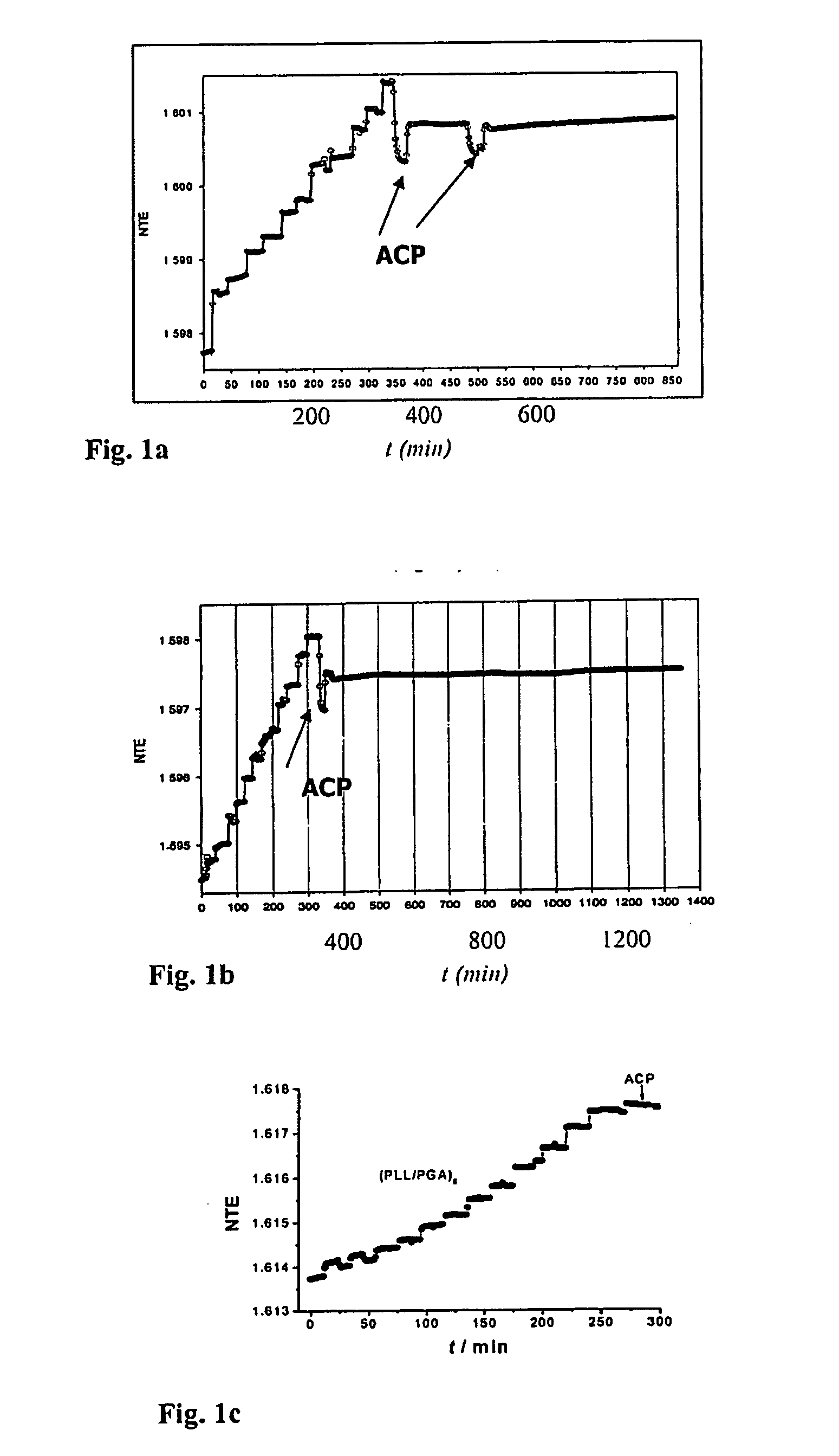
Buildup of SAPF and Adsorption of Amorphous Calcium Phosphate on Glass Plates.

[0045] Materials and methods: Poly(L-lysine) (PLL, MW 3.26×10⁴ Da), poly(L-glutamic acid) (PGA, MW 7.2×10⁴ Da), tris(hydroxymethyl) aminomethane (TRIS), 2-(N-morpholino) ethanesulfonic acid (MES), N-2-Hydroxyethylpiperazine-N′-2-ethanesulfonic acid (HEPES), and NaCl from Sigma, and ultrapure water, UPW (Milli Q-plus system, Millipore or Barnstead) were used. MES / TRIS / NaCl or HEPES buffer solutions of pH 7.4 were prepared as follows: MES / TRIS / NaCl buffer: 25 mmol of MES, 25 mmol of TRIS and 100 mmol of NaCl were dissolved in 1 liter of UPW. HEPES / NaCl buffer: 25 mmol of HEPES and 150 mmol NaCl were dissolved in 1 l of UPW. Polyelectrolyte solutions were always freshly prepared by direct dissolution of the respective adequate weights in filtered buffer solutions. Suspensions of ACP were freshly prepared for each experiment by rapidly mixing equal volumes of 3, 5 or 10 mmolar equimolar solutions of calcium ...

example 2

Build-Up of SAPF on Ti Plates and Deposition of ACP Particles Upon Them.

[0050] Materials and Methods: Pure titanium plates, were received courtesy of Dentaurum, J. P. Winkelstroeter AG, Germany (Titanium ASTM grade 4, diameter 15 mm, thickness 1.5 mm, machine polished to a surface roughness Ra 0.4 μm, Rmax 3.0 μm and cleaned in perchloroethylene) and courtesy of SAMO S.p.A., Italy (Titanium ASTM grade 2, 1×1 cm, thickness 1.5 mm, chemically etched by SAMO). Before coating, plates were sonicated subsequently in acetone (p.a.), ethanol (p.a.) and three times in UPW. Each procedure lasted 10-15 min. XRD spectra of the bare plates showed only peaks characteristic of Ti.

[0051] Material A: (PLL / PGA)i and (PLL / PGA)iPLL (i=9 or 14) multilayers were deposited as described in Example 1, using 1 ml of the respective solutions of PLL, PGA and HEPES / NaCl buffer pH 7.4. The plates with adsorbed multilayers were washed with buffer before depositing ACP particles. Plates were dipped three times ...

example 3

Coatings C and D Obtained by Build-Up of SAPF+ACP on Ti Plates and In-Situ Growth of OCP Crystals.

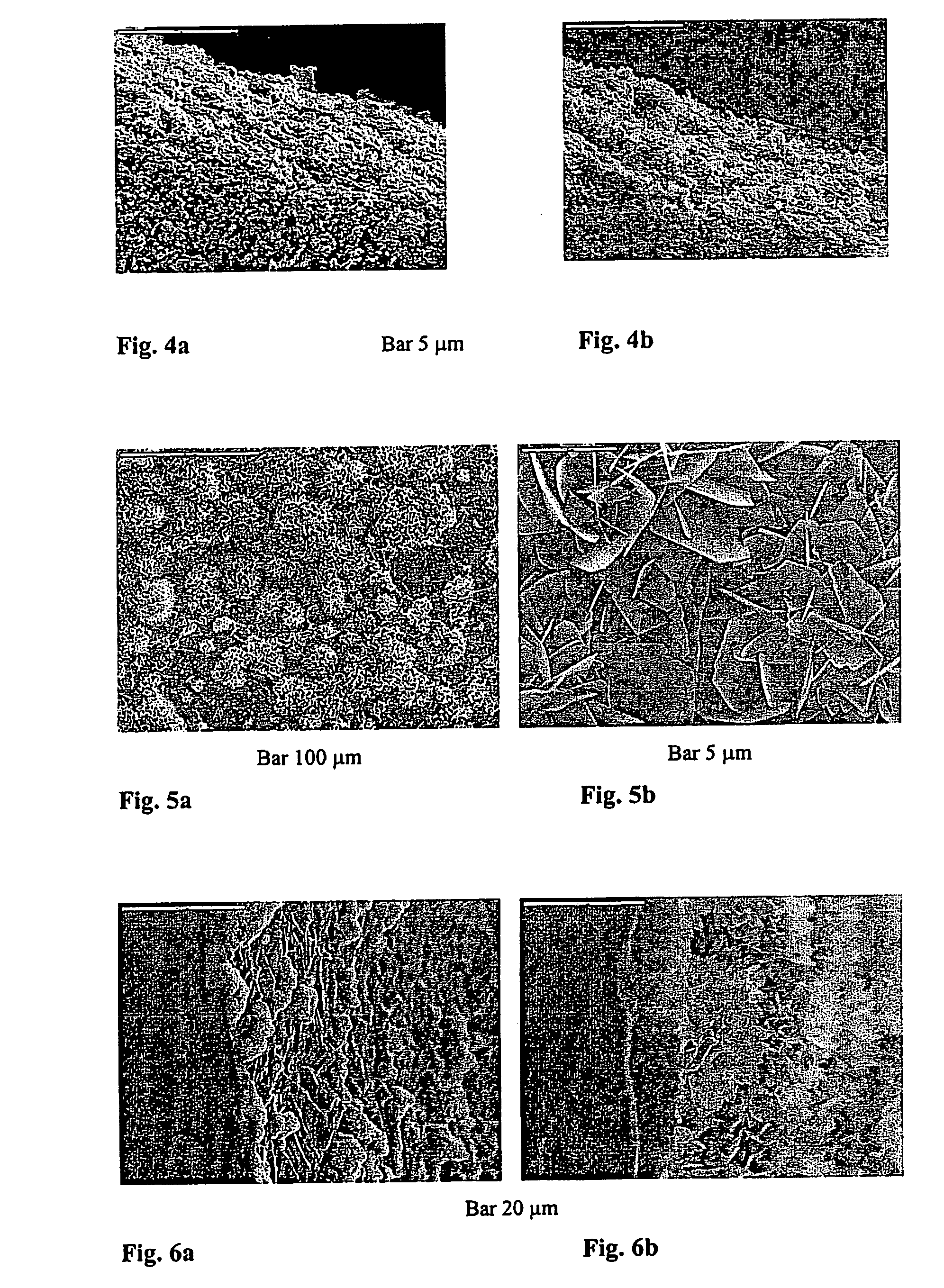
[0055] Coatings C and D: Materials A and B, respectively, were prepared on Ti plates as described in Example 2. Thus prepared plates were immersed into a calcifying solution (2.8 mmol / 1 CaCl2, 2 mmol / 1 Na2HPO4, 25 mmol / 1 HEPES, 150 mmol / 1 NaCl, pH 7.4) for 48 hours. By this procedure material A converted into coating C, whereas material B gave coating D. After the crystallizing procedure all plates were washed with buffer, dried in a stream of nitrogen and kept at 4° C. until further analysis by X-ray powder diffraction and SEM. The adhesive tape test was conducted according to ASTM D 3359-92a and the tested specimens were observed with SEM.

[0056] Reference is made now to FIG. 5 showing SEM micrographs of coating C. Large, well developed, plate-like crystals, oriented perpendicular to the substrate were obtained. Apparently, the crystals grew from the previously deposited aggregated ...


PUM

PropertyMeasurementUnit
temperatureaaaaaaaaaa
MWaaaaaaaaaa
pHaaaaaaaaaa

Abstract

The present invention provides inorganic-organic nanocomposite coatings for implant materials and methods for the production thereof. The coatings consist of a sequentially adsorbed polyelectrolyte film (SAPF) intergrown with calcium phosphate crystals. The substrate is selected from glass, polymer, metal or metal alloys. The SAPFs consist of successions of positively and negatively charged monolayers, comprising biocompatible polyelectrolytes, preferably polyaminoacids. The calcium phosphate crystals may comprise octacalcium phosphate, calcium deficient apatites, carbonate apatites, hydroxyapatite, or mixtures thereof, with particle sizes 50 nm to 2 μm. The inorganic phase is grown “in situ” within the polyelectrolyte organic matrix.

Description

FIELD OF THE INVENTION [0001] The invention generally relates to organic-inorganic nano-composite coatings for implant materials, mainly referring to orthopedic and dental implants, and to methods of preparation thereof. BACKGROUND OF THE INVENTION [0002] While most metals and metal alloys meet many of the biomechanical requirements of load bearing implants, they are bioinert or biotolerant and thus show poor or nonexistent interfacial bonding between the metallic surface and the surrounding bone. To alleviate this problem, different surface coatings consisting of calcium phosphates have been applied. Coating methods previously employed with some success include plasma spraying, which gives tight adhesion between hydroxyapatite and the metal plate. Drawbacks of this method are that it requires costly equipment and high processing temperatures. The high temperatures employed cause significant structural alterations in the coatings, which may result in mechanical failure at the interf...

Claims


Application Information

Patent Timeline
Patent Type & Authority Applications(United States)
IPC IPC(8): B32B5/16A61F2/28A61F2/00A61L27/32A61L27/34A61L27/46
CPCA61F2/30767Y10T428/258A61F2002/30535A61F2250/0058A61F2310/00017A61F2310/00023A61F2310/00071A61F2310/00089A61F2310/00095A61F2310/00107A61F2310/00131A61F2310/00143A61F2310/00179A61F2310/00329A61F2310/00796A61L24/0084A61L27/32A61L27/34A61L27/46A61L2400/12Y10T428/25A61F2/3094F16C2240/64
Inventor FUREDI-MILHOFER, HELGAOFIR, PAZIT BAR YOSEFSIKIRIC, MAJA DUTOURGERGELY, CSILLACUISINIER, FREDERIC
Owner YISSUM RES DEV CO OF THE HEBREWUNIVERSITY OF JERUSALEM LTD
Why Eureka
Try Eureka