System for improving crude oil

a crude oil and oil technology, applied in the direction of hydrocarbon oil cracking process, separation process, filtration separation, etc., can solve the problems of complex and expensive process, distillation process produced only a certain amount of gasoline, and the cost of a refining plant can easily exceed one billion dollars, so as to improve crude oil and improve crude oil. , the effect of enhancing crude oil

Inactive Publication Date: 2006-10-19
LJC TECH
View PDF23 Cites 59 Cited by
  • Summary
  • Abstract
  • Description
  • Claims
  • Application Information

AI Technical Summary

Benefits of technology

[0040] The present invention discloses a method and apparatus for enhancing crude oil. Specifically, the present invention includes a pneumatic pressure source which transports crude into a separator. The crude is placed under pressure sufficient to drive the crude into and through the filter media within the separator. As the crude passes through the filtration media, it experiences cavitation effects. The cavitation effects impart mechanical and thermal energy that assists in breaking or cracking the hydrocarbons into more valuable lighter hydrocarbons. The treated crude can then be transported to a collection tank. The particulate matter or build-up material retained on and within the filter media may be removed by the instantenous reverse pressurization of the separator thereby forcing the build-up material away from contact with the filter media and into a concentrator or setting tank, either of which can dewater, dry, and / or further process the build-up material as desired. The present invention thereby addresses the need for a less expensive and more flexible system for enhancing crude oil. In one aspect, the invention transforms crude oil having an API gravity of 26 into crude oil having an API gravity of 35.

Problems solved by technology

The refining process adds tremendous value to the produced oil, but is a complicated and expensive process.
The cost of a refining plant can easily exceed one billion dollars.
However, distillation processes produced only a certain amount of gasoline from crude oil.
The $20 spread between these values is caused by the additional cost of refining required for the heavy crude oil.
Hydrogen sulfide is a primary contributor to corrosion in refinery processing units.
Moreover, the corrosive sulfur compounds have an obnoxious odor.
Pyrophoric iron sulfide results from the corrosive action of sulfur compounds on the iron and steel used in refinery process equipment, piping, and tanks.
The combustion of petroleum products containing sulfur compounds produces undesirables such as sulfuric acid and sulfur dioxide.
The decomposition of nitrogen compounds in catalytic cracking and hydrocracking processes forms ammonia and cyanides that can cause corrosion.
Salt corrosion is caused by the hydrolysis of some metal chlorides to hydrogen chloride (HCl) and the subsequent formation of hydrochloric acid when crude is heated.
Hydrogen chloride may also combine with ammonia to form ammonium chloride (NH4Cl), which causes fouling and corrosion.
(heating crude oil above these temperatures may cause undesirable thermal cracking).
The cost of building a typical refining plant is staggering and no new refineries have been built in the U.S. since the 1970s.
A refinery also tends to be inflexible once designed.
In addition, refineries are expensive to operate with all of the energy requirements that the boilers at the various fractionation towers require, catalyst beds that get fouled, heat exchangers that get fouled, etc.
Much of the required preventive maintenance cannot be performed during the operation of the various refinery untis, thus the entire refinery must be shut down for a maintenance period every so often.
These expensive turnarounds require extensive planning and as well as manpower resources.
Further, it should be noted that while the refinery is shut down, it is not producing any income.

Method used


Image

  • System for improving crude oil
  • System for improving crude oil
  • System for improving crude oil

Examples


Embodiment Construction

[0079] The use of filtration media to produce improvement in crude oil profiles is both novel and a significant improvement over existing traditional distillation systems. Referring now to FIG. 4, a schematic diagram illustrating the interaction of the functional components of the system is depicted in accordance with the present invention. A crude oil is placed in a storage tank 401. This crude oil may include sulfur compounds, contaminated water, industrial solvents, or any similar fluid or solid from which sub-fractions are to be separated.

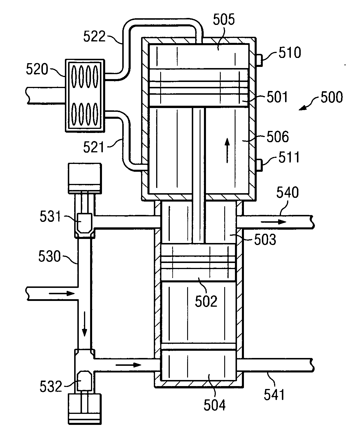
[0080] The filtration process begins by drawing the crude oil from the starting tank 401 by means of a first pneumatic pump 410. The pneumatic pump 410 alternately draws the crude oil through two poppet valves 411, 412 via the upward and downward motion of the plunger 413, and alternately pumps the fluid through two out lines 414, 415. As the plunger 413 rises (as show in the present example), fluid is drawn through poppet valve 412. Simultane...


PUM

PropertyMeasurementUnit
pressureaaaaaaaaaa
pressureaaaaaaaaaa
temperaturesaaaaaaaaaa

Abstract

Crude oil can be refined through a filtration media. Cavitation bubbles having localized areas of very high temperatures and pressures may be created thereby causing several physical and chemical phenomena, including thermal cracking of carbon-carbon bonds as the crude moves through the flux cartridge membrane. Heavy hydrocarbons are residues are thereby cracked into smaller lowering boiling molecules having a higher API gravity. Once the relatively smaller hydrocarbons pass through the flux cartridge membrane into the flux cartridge, the effluent can be routed to a second separator annulus. It should also be pointed out that lighter hydrocarbons formed can volatilize and special provisions may be needed to efficiently capture these gases.

Description

PRIORITY CLAIM [0001] This application claims the benefit of and priority to U.S. Provisional Application Ser. No. 60 / 672,187, which was filed on Apr. 15, 2005, which claims the benefit of and priority to co-pending U.S. patent application Ser. No. 11 / 042,235 which was filed on Jan. 25, 2005, which claims the benefit of and priority to U.S. patent application Ser. No. 10 / 820,538, filed on Apr. 8, 2004, which claims the benefit of and priority to U.S. Provisional Application No. 60 / 540,492, filed Jan. 30, 2004, the disclosures of which are incorporated herein by reference.BACKGROUND OF THE INVENTION [0002] 1. Technical Field [0003] The present invention relates to a system for improving crude oil and specifically to a method that does not involve the use of traditional distillation. Instead, the crude oil is filtered through a tight filtration media. The pressures and temperatures produced within the media break the longer hydrocarbon chains within the crude oil mixture, producing a ...

Claims


Application Information

Patent Timeline
Patent Type & Authority Applications(United States)
IPC IPC(8): C10G9/00C10G9/26C10G9/42B01D29/00B01D21/24
CPCC10G9/00C10G31/09C10G9/08
Inventor JOHNSON, RAYMOND FORD
Owner LJC TECH
Why Eureka
Try Eureka