Aromatic amine derivative and organic electroluminescence device using the same

a technology of organic electroluminescence and amine, which is applied in the direction of discharge tube luminescnet screen, other domestic articles, natural mineral layered products, etc., can solve the problems of large energy barrier between the transporting layer and the light-emitting layer, difficulty in achieving a luminance high enough to be put into practical use, and inability to achieve a device with a high luminance to achieve the effect of practical use, high emission luminance, and high heat resistan

Inactive Publication Date: 2006-11-09
IDEMITSU KOSAN CO LTD
View PDF7 Cites 66 Cited by
  • Summary
  • Abstract
  • Description
  • Claims
  • Application Information

AI Technical Summary

Benefits of technology

[0015] Each of the aromatic amine derivative of the present invention and the organic EL device using the derivative has high emission luminance, high heat resistance, excellent high-temperature storage stability, and a long lifetime.

Problems solved by technology

A reduction in thickness has been effective in reducing a driving voltage, but has not attained a device having luminance high enough to be put into practical use.
However, the organic EL device has, for example, practically insufficient emission luminous and practically insufficient durability against the deterioration of the device with time due to long-term use, so the additional improvement of the device has been requested.
It is difficult to achieve such half life particularly in the case of blue light emission.
In addition, an energy barrier upon hole injection between the hole-transporting layer and the light-emitting layer is large.
Therefore, the conventional hole-transporting layer has not allowed stable hole injection, so the improvement of the layer has been requested.
In addition, it has been pointed out that the storage performance of the organic EL device at a high temperature equal to or higher than 100° C. is problematic on the precondition that the device is mounted on a vehicle.
However, this approach has been still insufficient to realize good storage performance at a high temperature.
Furthermore, there has been a problem in that an exciplex occurs as an interaction between the hole-transporting layer and the light-emitting layer to deteriorate the luminance of the device.

Method used


Image

  • Aromatic amine derivative and organic electroluminescence device using the same
  • Aromatic amine derivative and organic electroluminescence device using the same
  • Aromatic amine derivative and organic electroluminescence device using the same

Examples


synthesis example 1

Synthesis of Compound (1)

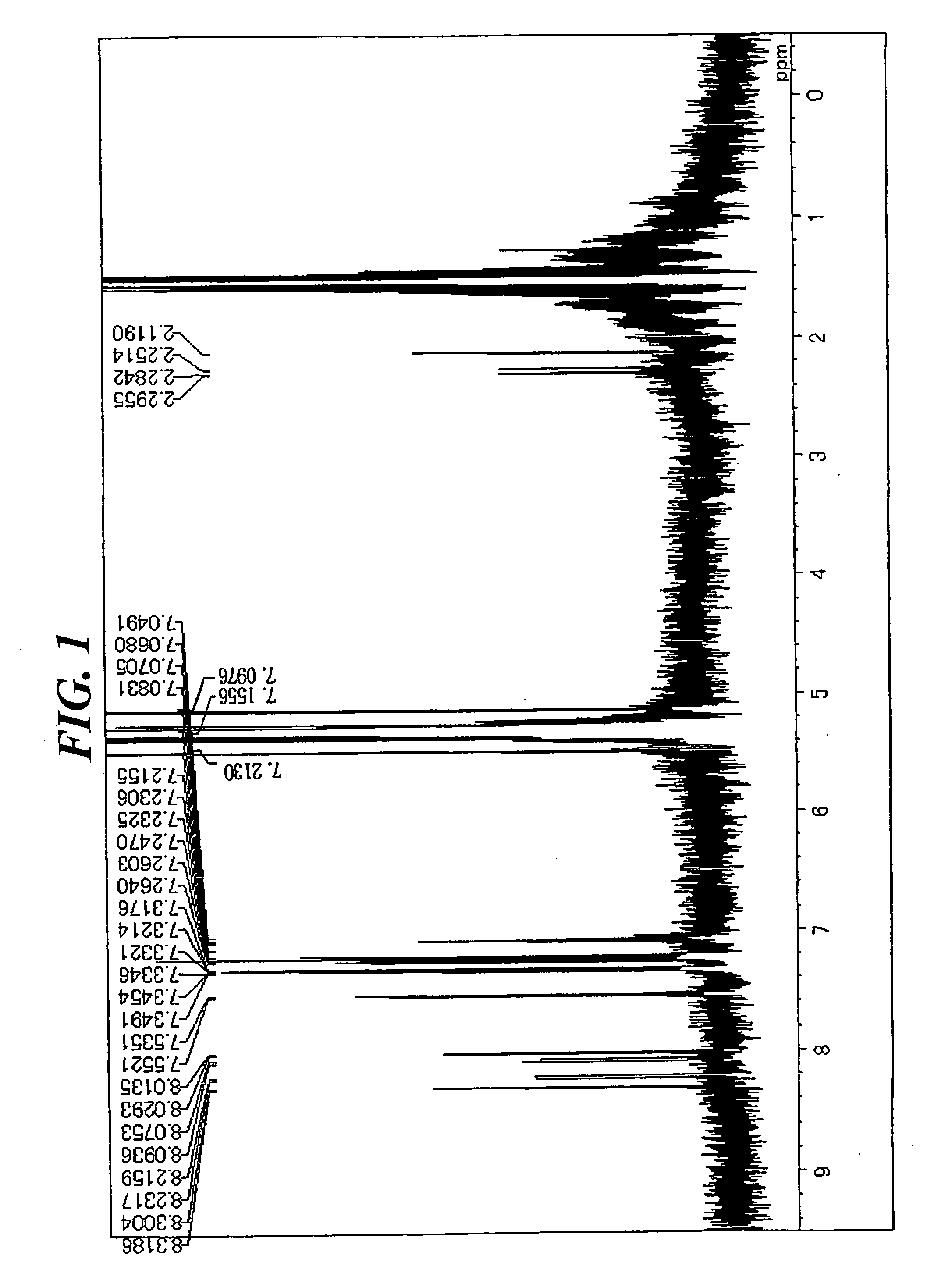
[0076] In a stream of argon, 5.2 g (14 mmol) of 1,6-dibromopyrene, 10 g (35 mmol) of 4-(diphenylamino)phenyl boronic acid, 0.8 g (0.7 mmol) of tetrakistriphenylphosphine palladium, an aqueous solution containing 7 g (65 mmol) of sodium carbonate in 33 mL of water, and 70 mL of toluene were added to a 300-mL three-necked flask equipped with a cooling pipe, and the whole was refluxed under heat for 8 hours. After the completion of the reaction, a precipitated crystal was filtered out and washed with 50 mL of toluene and 100 mL of methanol. The resultant coarse crystal was recrystallized with toluene, whereby 8 g of a white crystal were obtained. The crystal was identified as Compound (1) through the measurement of a 1H-NMR spectrum (FIG. 1) and a field desorption-mass spectrum (FD-MS) (80% yield). The 1H-NMR spectrum was measured by means of a DRX-500 (a heavy methylene chloride solvent) manufactured by Brucker (the same holds true for the following synthesis...

synthesis example 2

Synthesis of Compound (12)

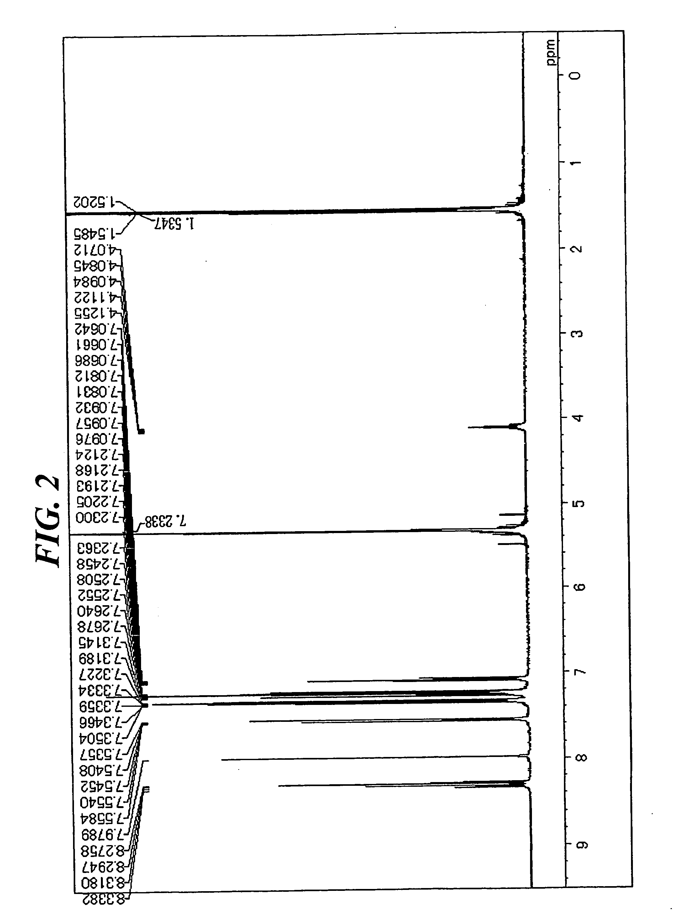
[0077] In a stream of argon, 5.8 g (13 mmol) of 1,6-diisopropyl-3,8-dibromopyrene, 9 g (31 mmol) of 4-(diphenylamino)phenyl boronic acid, 0.8 g (0.7 mmol) of tetrakistriphenylphosphine palladium, an aqueous solution containing 4 g (65 mmol) of sodium carbonate in 20 mL of water, 30 mL of toluene, and 20 mL of dimethoxyethane were added to a 300-mL three-necked flask equipped with a cooling pipe, and the whole was refluxed under heat for 8 hours. After the completion of the reaction, a precipitated crystal was filtered out and washed with 50 mL of toluene and 100 mL of methanol. The resultant coarse crystal was recrystallized with toluene, whereby 5 g of a white crystal were obtained. The crystal was identified as Compound (12) through the measurement of a 1H-NMR spectrum (FIG. 2) and a FD-MS (80% yield). The maximum absorption wavelength and maximum fluorescent wavelength of the resultant compound measured in a toluene solution were 390 nm and 452 nm, resp...

synthesis example 3

Synthesis of Compound (15)

[0078] (1) Synthesis of 1,6-diisopropyl-3,8-di(4-chlorophenyl) pyrene

[0079] In a stream of argon, 4.4 g (10 mmol) of 1,6-diisopropyl-3,8-dibromopyrene, 3.6 g (23 mmol) of 4-chlorophenyl boronic acid, 0.6 g (0.5 mmol) of tetrakistriphenylphosphine palladium, an aqueous solution containing 5 g (65 mmol) of sodium carbonate in 23 mL of water, and 45 mL of toluene were added to a 300-mL three-necked flask equipped with a cooling pipe, and the whole was refluxed under heat for 8 hours. After the completion of the reaction, an organic layer was washed with water and dried with magnesium sulfate. After that, the solvent was distilled off by means of a rotary evaporator. Thus, 5 g of 1,6-diisopropyl-3,8-di(4-chlorophenyl)pyrene of interest were obtained (a yellow crystal, 80% yield).

[0080] (2) Synthesis of Compound (15)

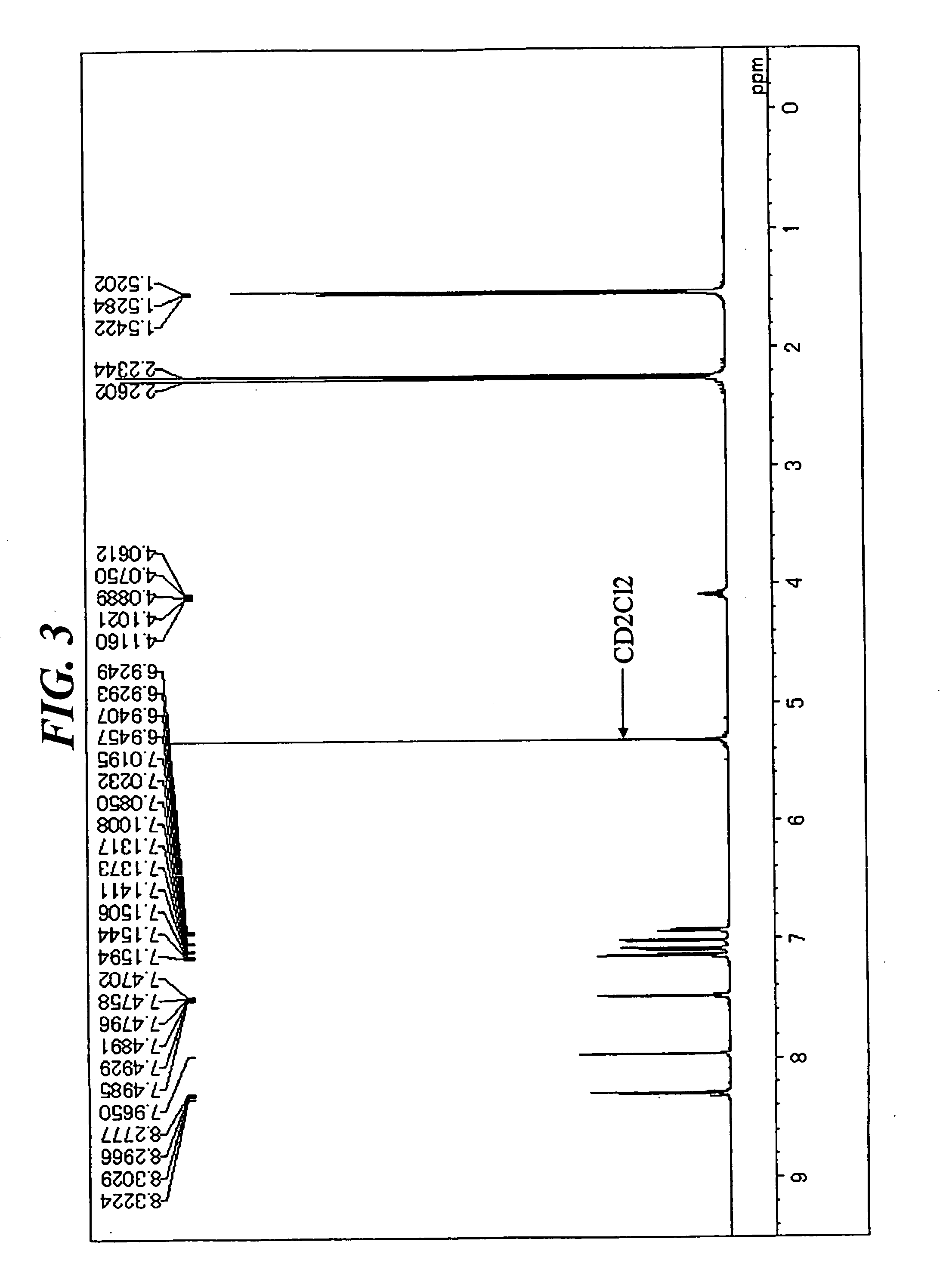
[0081] In a stream of argon, 4.5 g (9 mmol) of 1,6-diisopropyl-3,8-di(4-chlorophenyl)pyrene, 4.2 g (19 mmol) of bis(3,4-dimethylphenyl)amine, 0....


PUM

PropertyMeasurementUnit
thicknessaaaaaaaaaa
luminanceaaaaaaaaaa
energy gapaaaaaaaaaa

Abstract

To provide an organic electroluminescence device having high emission luminance, high heat resistance, excellent high-temperature storage stability, and a long lifetime, and an aromatic amine derivative for realizing the device. Provided are a novel aromatic amine derivative having a specific structure and an organic electroluminescence device including: a cathode; an anode; and one or multiple organic thin film layers including at least a light-emitting layer, the one or multiple organic thin film layers being interposed between the cathode and the anode, in which at least one layer of the one or multiple organic thin film layers contains the aromatic amine compound alone or as a component of a mixture.

Description

TECHNICAL FIELD [0001] The present invention relates to an aromatic amine derivative and an organic electroluminescence (EL) device using the same. More specifically, the present invention relates to an organic EL device having high emission luminance, high heat resistance, excellent high-temperature storage stability, and a long lifetime and to an aromatic amine derivative for realizing the organic EL device. BACKGROUND ART [0002] An organic EL device using an organic substance has been used as the flat luminous body of a wall hanging television or as a light source for, for example, the backlight of a display, and has been vigorously developed. [0003] The electroluminescence phenomenon of an organic material was observed in an anthracene single crystal by Pope et al. in 1963 (J. Chem. Phys. 38 (1963) 2042). In 1965, Helfinch and Schneider succeeded in observing relatively strong injection-type EL by means of a solution electrode system having good injection efficiency (Phys. Rev. ...

Claims


Application Information

Patent Timeline
Patent Type & Authority Applications(United States)
IPC IPC(8): H01L51/54H05B33/12C07C211/43C07D209/82
CPCC07C211/54Y10S428/917C07C211/60C07C211/61C07C2102/10C09K11/06C09K2211/1007C09K2211/1011C09K2211/1014H01L51/0054H01L51/006H01L51/0062H01L51/5012H01L51/5048H01L51/5092H05B33/14C07C211/58C07C2602/10H10K85/622H10K85/649H10K85/633H10K50/14H10K50/171H10K50/11H10K85/631
Inventor HOSOKAWA, CHISHIOKAWAMURA, MASAHIROFUNAHASHI, MASAKAZU
Owner IDEMITSU KOSAN CO LTD
Why Eureka
Try Eureka