Antireflection film

a technology of anti-reflection film and anti-abrasion resistance, which is applied in the direction of roads, instruments, traffic signals, etc., can solve the problems of low productivity, cumbersome production process, and disadvantageous high reflectance of anti-reflection film, and achieve excellent anti-reflection performance and excellent mechanical strength and abrasion resistance.

Inactive Publication Date: 2006-11-30
ASAHI KASEI KK
View PDF6 Cites 73 Cited by
  • Summary
  • Abstract
  • Description
  • Claims
  • Application Information

AI Technical Summary

Benefits of technology

[0015] In this situation, the present inventors have made extensive and intensive studies with a view toward solving the above-mentioned problems accompanying the prior art. As a result, the present inventors have unexpectedly found that the above objective can be attained by an antireflection film comprising silica particles and at least one binder compound, wherein the silica particles are bound together through the at least one binder compound, and wherein the antireflection film has a silica particle content of 30% by weight or less, an arithmetic mean surface roughness (Ra) of not more than 2 nm and a surface silicon atom content of 10 atom % or more. That is, it has surprising been found that the above-mentioned antireflection film not only exhibits excellent antireflection performance, but also has excellent properties with respect to mechanical strength and abrasion resistance. The present invention has been completed, based on this finding.

Problems solved by technology

An antireflection film having a single-layer structure or a double-layer structure has disadvantageously high reflectance.
However, when such an antireflection film comprised of three or more different layers is produced by any of the conventional methods, such as vacuum deposition and dip coating, disadvantages are caused in that the production process is cumbersome and also the productivity is low.
However, of these commercially available optical parts, the number of those optical parts having both a minimum reflectance of 2% or less and practically satisfactory properties with respect to mechanical strength and durability, is very small.
The reason why such effect can be obtained is that the presence of the minute dents and bumps on the surface of the antireflection film can decrease the practical contact area between the antireflection film and an object which placed in contact with the surface of the antireflection film.
However, an antireflection film having such a surface structure has posed a problem in that a stress applied to such a roughened surface of the antireflection film is inevitably mainly focused on the minute “peak top” portions (i.e., dents) of the roughened surface and, hence, the surface portion of the antireflection film is partially scraped off and / or the antireflection film is partially crushed in the thicknesswise direction, leading to a partial lowering of thickness of the antireflection film, and this will cause an inadvertent change in the color tone of the antireflection film.
This increase in the surface roughness poses problems not only in that there occurs an increase in the frictional resistance when the antireflection film is placed in contact with an object, but also in that there occurs an increase in the coming off of silica particles from the surface of the antireflection film, thus leading to even a lowering of the abrasion resistance (and not an increase in the abrasion resistance).
Thus, in the conventional techniques, it is very difficult to control the surface morphology and surface hardness of an antireflection film.
It is believed that, by such method, the practical performance of an antireflection film cannot be satisfactorily evaluated.
Such results of the evaluation cannot be considered to show that the antireflection film exhibits a satisfactory practical performance.
In these patent documents, an antireflection film having a low refractive index and a low reflectance is obtained, but the abrasion resistance of the antireflection film is still unsatisfactory.
As described hereinabove, there has not yet been able to be obtained an antireflection film which not only exhibits excellent antireflection performance, but also has satisfactory properties with respect to mechanical strength and abrasion resistance.

Method used


Image

  • Antireflection film
  • Antireflection film
  • Antireflection film

Examples


synthesis example 1

[0185] 89.1 g of an aqueous dispersion of moniliform silica strings which each comprise primary silica particles having an average particle diameter of about 12 nm and which have an average length of about 100 nm (trade name: Snowtex® OUP; manufactured and sold by Nissan Chemical Industries, Ltd., Japan) (solid silica content: 15.5% by weight), 68.1 g of a silica sol containing spherical silica particles having an average particle diameter of about 10 nm (trade name: Snowtex® OS; manufactured and sold by Nissan Chemical Industries, Ltd., Japan) (solid silica content: 20.3% by weight)) and 75.7 g of ethanol were mixed together at room temperature, and 17.1 g of 3-methacryloxypropyltrimethoxysilane (trade name: Sila-Ace; manufactured and sold by Chisso Corporation, Japan) was added thereto. The resultant mixture was stirred at 25° C. for 4 hours to effect a reaction, thereby obtaining a reaction mixture. On the other hand, 2 g of Irgacure® 369 (manufactured and sold by Ciba Specialty ...

synthesis example 2

[0186] 92.9 g of a dispersion of tin-containing indium oxide particles (trade name: ELCOM V-2506; manufactured and sold by Catalysts & Chemicals Industries Co., Ltd., Japan) (solids content: 20.5% by weight) and 125.3 g of a dispersion of zinc oxide particles (trade name: ZNAP15WT %-G0; manufactured and sold by C. I. KASEI CO., LTD., Japan) were mixed together to obtain a mixture. On the other hand, 304.2 g of isopropyl alcohol, 33.8 g of ethylene glycol monobutyl ether and 23.9 g of water were mixed together to obtain a mixed solvent. Further, 9.9 g of an acrylic ultraviolet-curable resin (trade name: SANRAD RC-600; manufactured and sold by Sanyo Chemical Industries, Ltd., Japan) and 9.9 g of methyl ethyl ketone were mixed together to obtain a solution. Then, to the above-obtained mixture of a dispersion of tin-containing indium oxide particles and a dispersion of zinc oxide particles were added the above-obtained mixed solvent and the above-obtained solution in this order, and the...

example 1

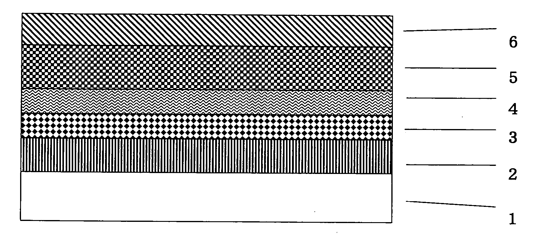
[0187] The transfer foil C shown in FIG. 1 was produced as follows.

[0188] A surface of a biaxially oriented polyethylene terephthalate film (provisional substrate) 1 (thickness: 50 μm) was coated with a 50% by weight methyl ethyl ketone solution of an acrylic UV curable resin (solids content: 100% by weight) (SANRAD (tradename) RC-600; manufactured and sold by Sanyo Chemical Industries, Ltd., Japan) using a bar coater (equipped with #7 rod; manufactured and sold by R. D. Specialties, Inc., U.S.A.). Then, the resultant coating on the polyethylene terephthalate film was cured by irradiating ultraviolet rays (integrated optical power: 250 mJ / cm2) using a UV curing machine (LC-6B type; manufactured and sold by Fusion UV Systems Japan K.K., Japan) under conditions wherein the intensity is 180 W, the rate of the conveyer is 12 m / minute and the distance from the light source is 53 mm. This UV irradiation operation was performed three times, thereby forming release layer 2 on the provision...


PUM

PropertyMeasurementUnit
Raaaaaaaaaaa
reflectanceaaaaaaaaaa

Abstract

An antireflection film comprising silica particles and at least one binder compound, which has a silica particle content of 30% by weight or more, an arithmetic mean surface roughness (Ra) of not more than 2 nm, and a surface silicon atom content of 10 atom % or more.

Description

BACKGROUND OF THE INVENTION [0001] 1. Field of the Invention [0002] The present invention relates to an antireflection film. More particularly, the present invention is concerned with an antireflection film comprising silica particles and at least one binder compound, wherein the silica particles are bound together through the at least one binder compound, and wherein the antireflection film has a silica particle content of 30% by weight or less, an arithmetic mean surface roughness (Ra) of not more than 2 nm and a surface silicon atom content of 10 atom % or more. The antireflection film of the present invention not only exhibits excellent antireflection performance, but also has excellent properties with respect to mechanical strength and abrasion resistance. Therefore, the antireflection film of the present invention is very advantageous for coating various optical substrates (such as lenses of eye-glass and display screens). [0003] 2. Prior Art [0004] Conventionally, as an antir...

Claims


Application Information

Patent Timeline
Patent Type & Authority Applications(United States)
IPC IPC(8): B32B27/18B32B33/00G02B1/11
CPCG02B1/111Y10T428/24942Y10T428/252Y10T428/259Y10T428/24372Y10T428/31504Y10T428/24994Y10T428/31786
Inventor OHASHI, TOSHIHIKOIOKA, TAKAAKI
Owner ASAHI KASEI KK
Why Eureka
Try Eureka