
Multi-segment photonic-crystal-rod waveguides for amplification of high-power pulsed optical radiation and associated method

a technology of photonic crystal rods and waveguides, applied in the field of high-power optical amplifiers and lasers, can solve problems such as degrading the beam quality

Inactive Publication Date: 2007-05-10
LOCKHEED MARTIN CORP
View PDF51 Cites 82 Cited by
  • Summary
  • Abstract
  • Description
  • Claims
  • Application Information

AI Technical Summary

Benefits of technology

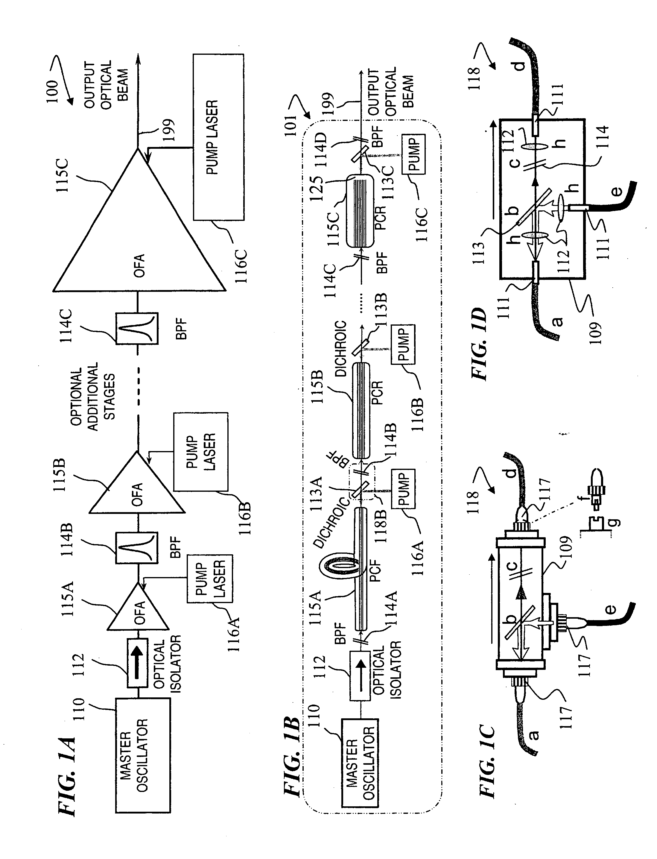
[0010] In some embodiments, the present invention provides pulsed fiber lasers and amplifiers for applications that require pulses that are a few nanoseconds long at multi-kHz pulse-repetition rates (PRR), exhibiting one or more of the following characteristics: high peak power (useful for applications such as, e.g., wavelength conversion, materials processing, and ranging), high pulse energy (useful for applications such as, e.g., illumination and imaging), and narrow spectral linewidth (useful for applications such as, e.g., remote sensing and wavelength conversion). The present invention provides fiber-based sources that generate higher pulse energies and peak powers than are conventionally available, while also achieving compactness, efficiency, and high beam quality.
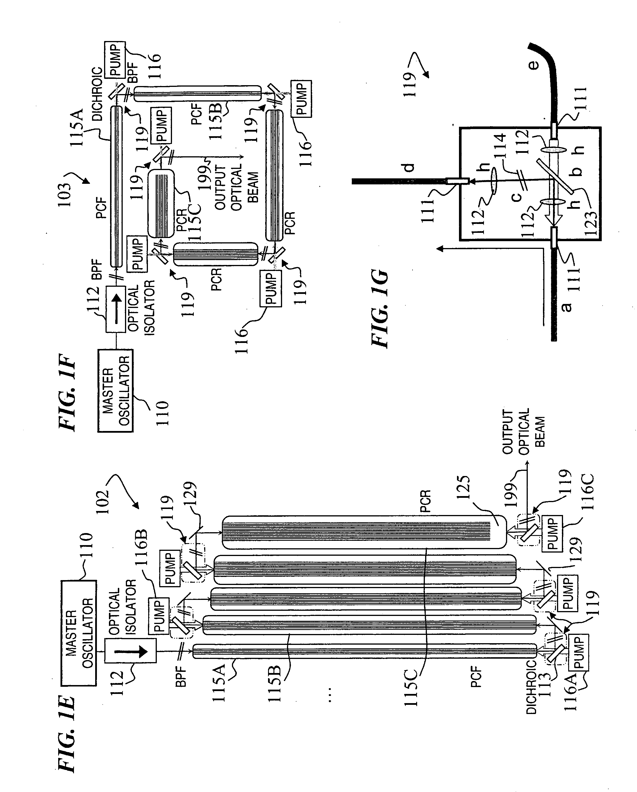
[0011] In some embodiments, the present invention provides high-power pulsed fiber lasers and amplifiers based on photonic-crystal-fiber technology, which produce high peak power (>500 kilowatt (kW)) linearly polarized output beams of near-diffraction-limited beam quality and narrow spectral linewidth that can be effectively used for generation of high-peak-power visible and ultraviolet radiation by means of frequency conversion in nonlinear crystals. In some embodiments, the outputs from several linearly polarized, spectrally narrow, high-peak-power fiber lasers and / or amplifiers based on the same technology and arranged in a suitable pattern can be combined spectrally by using an external dispersive optical element to produce a beam of near-diffraction-limited beam quality and peak power / pulse energy approximately equal to the sum of the peak powers / pulse energies from each individual fiber laser / amplifier. The benefit of this beam-combination scheme is that it produces a peak power in a single beam that is much higher than the damage threshold for an individual fiber.
[0012] Optical fibers are waveguides, in which a certain number of transverse modes of radiation can exist and propagate with low loss. Different transverse modes correspond to different transverse profiles of optical intensity. In step-index fibers, the fundamental mode profile is very similar to a Gaussian. Fibers that support only this mode (usually referred to as “single-mode fibers”) inherently produce the best beam quality. For a given refractive index step between core and cladding, the number of transverse modes supported by a fiber is proportional to the core diameter. Therefore, large-core fibers tend to be multimode, which degrades the beam quality.

Problems solved by technology

Therefore, large-core fibers tend to be multimode, which degrades the beam quality.

Method used


Image

  • Multi-segment photonic-crystal-rod waveguides for amplification of high-power pulsed optical radiation and associated method
  • Multi-segment photonic-crystal-rod waveguides for amplification of high-power pulsed optical radiation and associated method
  • Multi-segment photonic-crystal-rod waveguides for amplification of high-power pulsed optical radiation and associated method

Examples


Embodiment Construction

[0076] Although the following detailed description contains many specifics for the purpose of illustration, a person of ordinary skill in the art will appreciate that many variations and alterations to the following details are within the scope of the invention. Accordingly, the following preferred embodiments of the invention is set forth without any loss of generality to, and without imposing limitations upon the claimed invention.

[0077] In the following detailed description of the preferred embodiments, reference is made to the accompanying drawings that form a part hereof, and in which are shown by way of illustration specific embodiments in which the invention may be practiced. It is understood that other embodiments may be utilized and structural changes may be made without departing from the scope of the present invention.

[0078] The leading digit(s) of reference numbers appearing in the Figures generally corresponds to the Figure number in which that component is first intr...


PUM


Abstract

A method and apparatus use a photonic-crystal fiber having a very large core while maintaining a single transverse mode. In some fiber lasers and amplifiers having large cores problems exist related to energy being generated at multiple-modes (i.e., polygamy), and of mode hopping (i.e., promiscuity) due to limited control of energy levels and fluctuations. The problems of multiple-modes and mode hopping result from the use of large-diameter waveguides, and are addressed by the invention. This is especially true in lasers using large amounts of energy (i.e., lasers in the one-megawatt or more range). By using multiple small waveguides in parallel, large amounts of energy can be passed through a laser, but with better control such that the aforementioned problems can be reduced. An additional advantage is that the polarization of the light can be maintained better than by using a single fiber core.

Description

CROSS-REFERENCE TO RELATED APPLICATIONS [0001] This invention claims benefit of U.S. Provisional Patent Application 60 / 703,822 filed on Jul. 29, 2005, titled “FIBER-BASED OPTICAL SOURCE FEATURING A LARGE-CORE, RARE-EARTH-DOPED PHOTONIC CRYSTAL FIBER FOR GENERATION OF HIGH POWER PULSED RADIATION,” and U.S. Provisional Patent Application 60 / 746,166 filed on May 1, 2006, titled “FIBER- OR ROD-BASED OPTICAL SOURCE FEATURING A LARGE-CORE, RARE-EARTH-DOPED PHOTONIC-CRYSTAL DEVICE FOR GENERATION OF HIGH-POWER PULSED RADIATION AND METHOD,” and U.S. Provisional Patent Application 60 / 797,931 filed on May 5, 2006, titled “FIBER- OR ROD-BASED OPTICAL SOURCE FEATURING A LARGE-CORE, RARE-EARTH-DOPED PHOTONIC-CRYSTAL DEVICE FOR GENERATION OF HIGH-POWER PULSED RADIATION AND METHOD,” which are each hereby incorporated by reference in their entirety. This application is also related to U.S. patent application Ser. No. 11 / 420,729 entitled “FIBER- OR ROD-BASED OPTICAL SOURCE FEATURING A LARGE-CORE, RAR...

Claims


Application Information

Patent Timeline
Patent Type & Authority Applications(United States)
IPC IPC(8): G02B6/02
CPCG02B6/02328G02B6/02347G02B6/02376G02B6/02385H01S3/06729H01S3/06741H01S3/06754H01S3/06758H01S3/094003H01S3/094007
Inventor DI TEODORO, FABIOBROOKS, CHRISTOPHER D.LEMAIRE, CHARLES A.
Owner LOCKHEED MARTIN CORP
Learn More