Pyroelectric sensor

a technology of pyroelectric sensors and sensors, applied in the field of capacitive ferroelectric elements, can solve the problems of large limited signal-to-noise differentiation ability of sensors, and large size of focal point arrays and supporting circuits, etc., to achieve the effect of reducing the dependence on thermal isolation, superior noise-to-signal ratio and sensitivity, and being environmentally friendly and robus

Active Publication Date: 2007-05-17
APTIV TECH LTD +1
View PDF2 Cites 40 Cited by
  • Summary
  • Abstract
  • Description
  • Claims
  • Application Information

AI Technical Summary

Benefits of technology

[0021] Objects, features and advantages of this invention include a pyroelectric sensor having superior noise-to-signal ratio and sensitivity thus enabling use of ferroelectric materials not previously considered for pyroelectric applications, and which have curie temperatures near or significantly above room temperature, are relatively inexpensive, do not require high temperatures to process, and are environmentally friendly and robust.
[0022] Moreover, the present invention decreases the dependence upon thermal isolation of the elements of the array from the silicon substrate, hence, the traditional air bridge may not be required thus reducing manufacturing process steps, decreasing cost by producing a higher yield of acceptable arrays, enabling wafer level fabrication, and reducing element size.
[0023] Yet further, utilization of a scene element and reference element with corresponding circuitry reduces the necessary output capacitance thus enabling placement of output capacitors on the chip which reduces the overall size of the array and supporting circuitry, enables a greater averaging of cycles thus increasing signal-to-noise ratio and prevents saturation of the signal output voltage.

Problems solved by technology

Unfortunately, this technique only represents a single cycle around a minor portion of the available signal energy as represented by the hysteresis loop area of FIG. 2.
As is apparent, this detection scheme utilizes only a small portion of the hysteresis loop, and therefore the sensors are limited in their ability to differentiate signal from noise.
Robust and relatively expensive system components, such as the chopper 12 and the amplifier 22 cannot increase the signal from noise, but only prevents further degradation.
Utilizing an output capacitor of sufficient capacitance limits the ability to place the capacitor on the chip and causes the focal point array and supporting circuitry to be larger than desired.
Unfortunately, very few of the known materials have curie temperatures near room temperature of approximately 22° C. Moreover, the materials listed above require high temperature processing and require expensive manufacturing processes; some such as BST are hard to grow, some contain lead which is environmentally unfriendly, and still others contain expensive scandium.
Unfortunately, the air bridge concept requires both a silicon manufacturing process and a ceramic process.
Moreover, the manufacturing process is expensive, produces a low yield of good arrays, requires inefficient single unit handling and is not capable of wafer-level fabrication.
Yet further, the element is limited in size reduction, which is increasingly important when viewing that a typical focal plane array, FPA, typically can have an array of 512×512 pixel elements.

Method used


Image

  • Pyroelectric sensor
  • Pyroelectric sensor
  • Pyroelectric sensor

Examples


Embodiment Construction

[0038] The following description of the preferred embodiments directed to an active pyroelectric sensor system is merely exemplary in nature, and is in no way intended to limit the invention or its applications or uses.

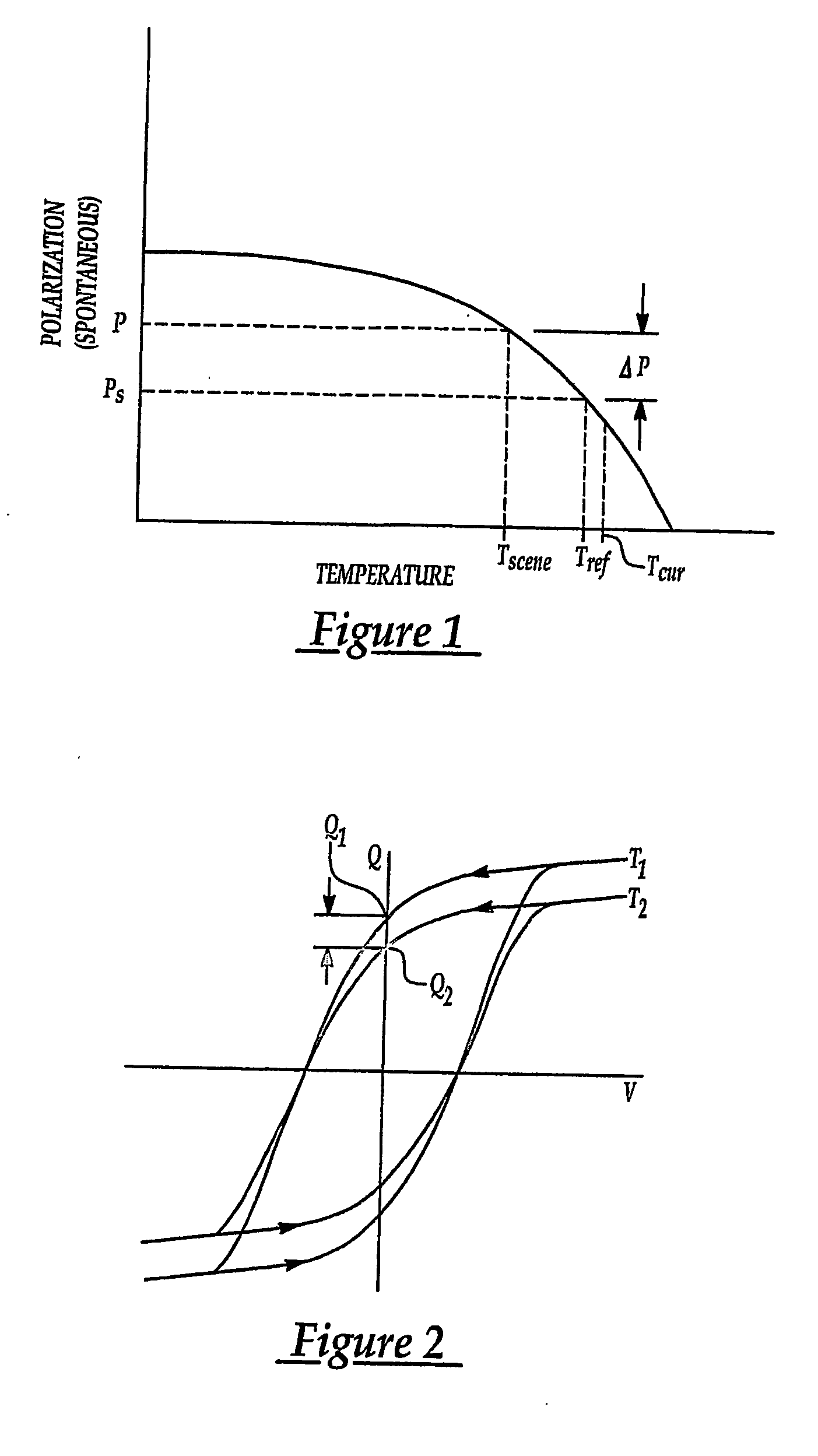
[0039] Because the conventional passive pyroelectric sensor designs discussed above do not switch Ps from its initial state during interrogation, closer analysis suggests that the large energy product of the ferroelectric material identified by the hysteresis loop is not typically fully exploited by the industry. The product of the remnant polarization Pr in the fully polarized state, and the coercive electric field Ec required to remove all such residual polarization, is generally identified as the energy product PrEc. This PrEc product has the dimensions of energy density, which serves to compare the “hardness” or energy storage capabilities of such materials. Hence, by employing Ps switching, this invention proposes in-part that the entire hysteresis loop may be t...


PUM


Abstract

A ferroelectric/pyroelectric sensor employs a technique for determining a charge output of a ferroelectric scene element of the sensor by measuring the hysteresis loop output of the scene element several times during a particular time frame for the same temperature. An external AC signal is applied to the ferroelectric scene element to cause the hysteresis loop output from the element to switch polarization. Charge integration circuitry, such as a combination output capacitor and operational amplifier, is employed to measure the charge from the scene element. Preferably, the ferroelectric of the scene element is made of an economical and responsive strontium bismuth tantalate, SBT, or derivative thereof, disposed directly between top and bottom electrodes. Because of the frequency characteristics of the sensor, created by the external AC signal, the element need not be thermally isolated from the silicon substrate by a traditional air bridge, which is difficult to manufacture, and instead is preferably thermally isolated by spin-on-glass, SOG. To prevent saturation of an output signal voltage of the sensor by excessive charge accumulation in an output capacitor, the sensor preferably has a reference element configured electrically in parallel with the scene element. When the voltage of the AC signal is negative the output capacitor is discharged by flowing current through the reference element thus interrogating the polarization of the reference element which is compared to and subtracted from the polarization of the scene element for each cycle. The polarization difference measured for each cycle over a set time period are summed by an integrating amplifier to produce a signal output voltage.

Description

RELATED APPLICATIONS [0001] This patent application claims benefit of U.S. Provisional patent application 60 / 449,505 filed Feb. 21, 2003.TECHNICAL FIELD [0002] This invention relates generally to pyroelectric sensors and, more particularly, to a capacitive ferroelectric element of the sensor having a temperature dependent polarization accentuated by the application of an external AC signal to the element and measured by a charge integration system of the sensor. BACKGROUND OF THE INVENTION [0003] A certain class of sensors configured into an array of pixilated capacitive elements make use of ferroelectric materials, and their pyroelectric effect for detection of temperature change. Sensors of this type have a wide range of applications, such as imaging in low visibility conditions, for example, poor weather conditions, night vision, etc. A ferroelectric material is a dielectric material that has a temperature dependent spontaneous electrical polarization. Each pixel element is therm...

Claims


Application Information

Patent Timeline
Patent Type & Authority Applications(United States)
IPC IPC(8): G01J5/00G01J5/34
CPCG01J5/34
Inventor MANTESE, JOSEPH V.SCHUBRING, NORMAN W.MICHELI, ADOLPH L.DE ARAUJO, CARLOS PAZMCMILLAN, LARRYCELINSKA, JOLANTA
Owner APTIV TECH LTD
Why Eureka
Try Eureka