Conductive paste for connecting thermoelectric conversion material

Inactive Publication Date: 2007-06-07
NAT INST OF ADVANCED IND SCI & TECH
View PDF4 Cites 23 Cited by
  • Summary
  • Abstract
  • Description
  • Claims
  • Application Information

AI Technical Summary

Benefits of technology

[0009] The present invention has been made to solve the above problems. A principal object of the invention is to provide a material for connecting thermoelectric materials which can achieve the connection of the thermoelectric material made of oxide with a low electr

Problems solved by technology

In Japan, only 30% of the primary energy supply is used as effective energy, with about 70% being eventually lost to the atmosphere as heat.
In this way, a vast amount of thermal energy is wastefully discarded, while acquiring only a small amount of energy by combustion of fossil fuels or other means.
However, the development of thermoelectric elements and thermoelectric modules has been delayed so far as compared to the development of thermoelectric materials.
However, such noble metal pastes are not suitab

Method used


Image

  • Conductive paste for connecting thermoelectric conversion material
  • Conductive paste for connecting thermoelectric conversion material
  • Conductive paste for connecting thermoelectric conversion material

Examples


Example

Example 1

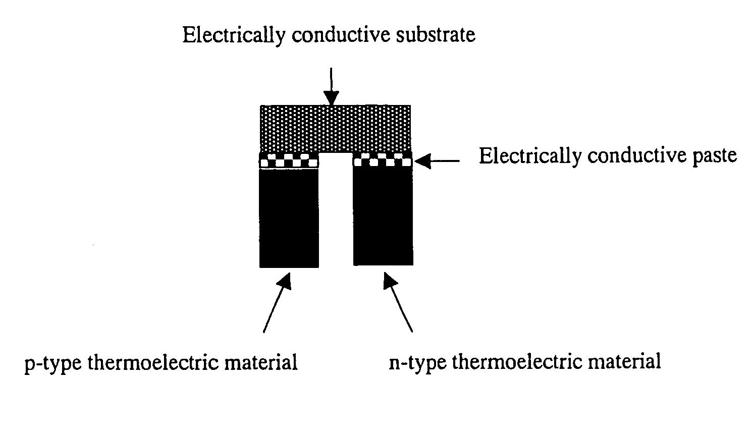
Production of P-Type Thermoelectric Material

[0164] A p-type thermoelectric material represented by the formula Ca2.7Bi0.3Co4O9.2 was produced according to the following method.

[0165] Initially, calcium carbonate (CaCO3), bismuth oxide (Bi2O3), and cobalt oxide (Co3O4) were weighed out in such a manner as to yield a Ca:Bi:Co ratio (atomic ratio) of 2.7:0.3:4 and thoroughly mixed. The mixture was placed into an alumina crucible and calcined in air at 1073 K(800° C.) for 10 hours. The calcinate was sufficiently mixed using an agate mortar and pestle.

[0166] The obtained powder was molded by pressing into a disk-like form with a diameter of 20 mm and thickness of about 2 mm to about 10 mm. The molded body was placed on a gold sheet laid on an alumina boat, and sintered in a 300 ml / minute oxygen stream at 1153 k (880° C.) for 20 hours. The sintered body thus obtained was crushed using an agate mortar and pestle.

[0167] The powder thus obtained was molded by pressing into a p...

Example

Examples 2 to 94

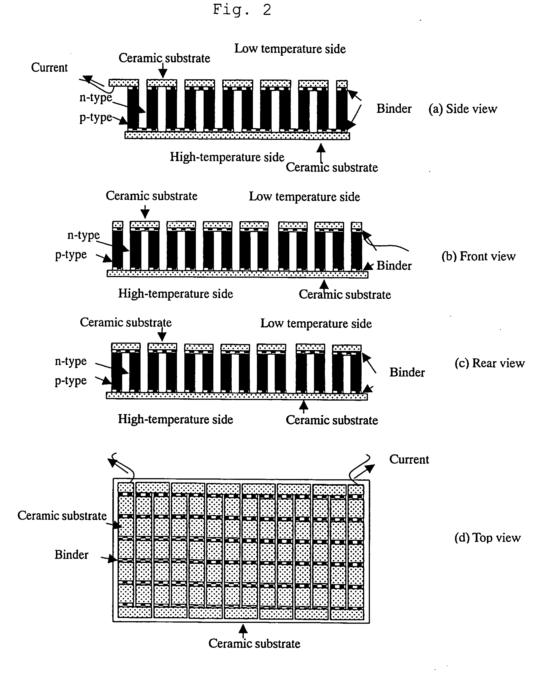
[0189] Thermoelectric elements were produced in the same manner as in Example 1 except that the materials represented by the formulae in Tables 1 to 7 were used as oxide powder(s) to be mixed in the electrically conductive pastes for connecting p-type thermoelectric materials; oxide powder to be mixed in the electrically conductive pastes for connecting n-type thermoelectric materials; p-type thermoelectric materials; and n-type thermoelectric materials. The thermoelectric performance of the thermoelectric elements obtained was evaluated. In each Table, the amount of oxide powder to be mixed in the electrically conductive paste is expressed in parts by weight per 100 parts by weight of silver powder.

[0190] Each Table shows open-circuit voltages measured when the temperatures of the high-temperature portion and the low temperature portion were 973 K and 500 K, respectively, and inner resistances measured when the temperature of the high-temperature portion was 973K....


PUM


Abstract

The present invention provides an electrically conductive paste for connecting thermoelectric materials, the paste comprising a specific powdery oxide and at least one powdery electrically conductive metal selected from the group consisting of gold, silver, platinum, and alloys containing at least one of these metals. By connecting a thermoelectric material to an electrically conductive substrate with the electrically conductive paste of the invention, a suitable electroconductivity is imparted to the connecting portion of the thermoelectric element. Further, the thermal expansion coefficient of the connecting portion can be made close to that of the thermoelectric material. Therefore, even when high-temperature power generation is repeated, separation at the connecting portion is prevented and a favorable thermoelectric performance can be maintained.

Description

TECHNICAL FIELD [0001] The present invention relates to an electrically conductive paste for connecting thermoelectric materials, a thermoelectric element obtained using the-paste, and a thermoelectric module. BACKGROUND OF THE INVENTION [0002] In Japan, only 30% of the primary energy supply is used as effective energy, with about 70% being eventually lost to the atmosphere as heat. The heat generated by combustion in industrial plants, garbage-incineration facilities or the like is lost to the atmosphere without conversion into other energy. In this way, a vast amount of thermal energy is wastefully discarded, while acquiring only a small amount of energy by combustion of fossil fuels or other means. [0003] To increase the proportion of energy to be utilized, the thermal energy currently lost to the atmosphere should be effectively used. For this purpose, thermoelectric conversion, which directly converts thermal energy to electrical energy, is an effective means. Such a thermoelec...

Claims


Application Information

Patent Timeline
IPC IPC(8): H01L35/34H01L35/00C01G51/00C01G53/00H01B1/08H01B1/16H01B1/22H01L35/08H01L35/22
CPCC01G51/006C01G51/66C01G53/006C01G53/68C01G53/70C01P2002/32C01P2002/34C01P2002/52C01P2004/51C01P2004/60C01P2004/61C01P2004/84C01P2006/40H01B1/08H01B1/16H01L35/08H01L35/22C01P2004/80H10N10/817H10N10/855
Inventor FUNAHASHI, RYOJI
Owner NAT INST OF ADVANCED IND SCI & TECH
Why Eureka
Try Eureka