Thin wear resistent coating

a technology of wear resistance and coating, applied in the direction of ion implantation coating, superimposed coating process, pigmenting treatment, etc., can solve the problems of accelerated wear of the layer and failure of the cohesion layer, and achieve the effect of improving the cutting performan

Inactive Publication Date: 2007-08-02
SECO TOOLS AB
View PDF13 Cites 22 Cited by
  • Summary
  • Abstract
  • Description
  • Claims
  • Application Information

AI Technical Summary

Benefits of technology

[0006] It has been found that, by balancing the chemical composition, the amount of thermal energy and the degree of ion induced surface activation during growth, growth rate, and pressure, layers containing h-MeX phase can be obtained which, compared to the prior a

Problems solved by technology

Therefore, if the degree of structural transformation of an applied (Ti,Al)N layer p

Method used


Image

  • Thin wear resistent coating
  • Thin wear resistent coating

Examples


example 1

[0050] Polished cemented carbide substrates with composition 93.5 wt-% WC-6 wt-% Co-0.5 wt-% (Ta,Nb)C were used. The WC grain size was about 1 μm and the hardness was 1630 HV10.

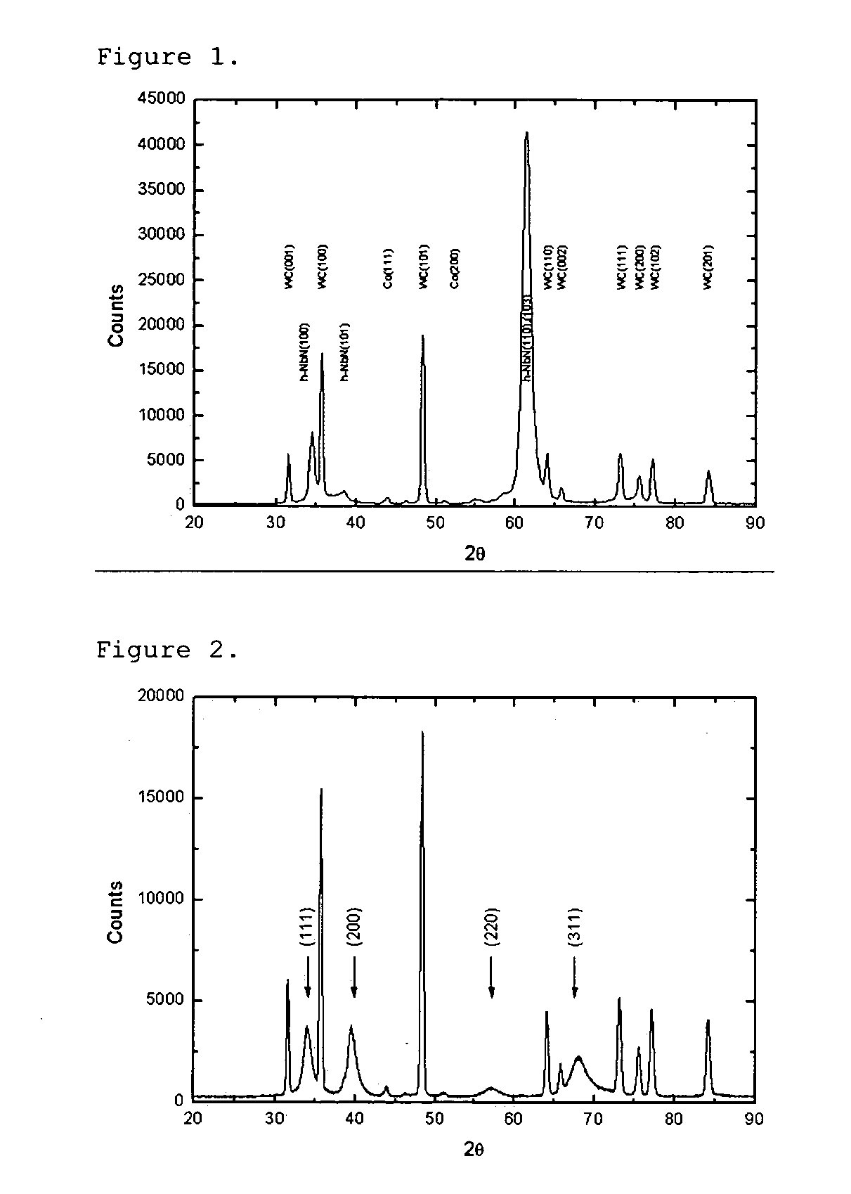
[0051] Before deposition, the substrates were cleaned in ultrasonic baths using alkali solution and alcohol and subsequently placed in the PVD-system using a fixture of one-fold rotation. The shortest cathode-to-substrate distance was 160 mm. The system was evacuated to a pressure of less than 2.0×10⁻³ Pa, after which the substrates were sputter cleaned with Ar ions. The layers were grown using arc evaporation of Nb and Zr cathodes (63 mm in diameter) mounted so a vertical metal composition gradient varied from Nb0.97Zr0.03 to Nb0.29Zr0.71 (measured by EDS). The nitrogen content (measured by EDS) of the variants containing h-AIN was between (Nb,Zr)N0.77-0.92. This means that the ratio R=(at-% X) / (at-% Me1+at-% Me2) is between 0.77 and 0.92 where X is N and Me1 is Nb and Me2 is Zr.

[0052] The deposition was c...

example 2

[0058] Cemented carbide exchangeable end mills of type MM12-12012-B90P-M05 with composition 90 wt-% WC-10 wt-% Co (WC grain size 0.8 μm) were coated using similar deposition conditions as in Example 1 (the name of the variants in Example 2 refers to variant names in Example 1 with similar composition). A fixture with three-fold rotation was used. The end mills were positioned at different levels in order to get different composition. The deposition period was adjusted from example 1 to 140 min in order to get 3.0 μm on the flank face. As a reference a TiN coated end mill of the same geometry and substrate was used, here called TiN. The layer thickness on the flank face on this variant was 1.4 μm.

[0059] A semi-finishing copy milling test was performed using the following cutting data:

[0060] Material: DIN X100CrMoV 5 1, 59 HRC

[0061] n=4050 rpm

[0062] ap=ae=0.9 mm

[0063] vf=900 mm / min

[0064] hm=0.015 mm

[0065] After 30 min in cut the maximum flank wear, Vbmax, was measured at two di...

example 3

[0067] A copy milling test using RDHW10T3M0T-MD06 inserts coated similarly as in Example 1 (variants A, C and E). The tool life was measured when the inserts were worn out as defined as when sparkles were created and the material got an uneven surface. Tool life is reported in table 3.

[0068] Material: DIN X155 CrMoV 12 1, hardened to 58 HRC

[0069] Dry machining

[0070] vc=250 m / min

[0071] fz=0,2 mm / tooth

[0072] ap=1 mm, ae 2 mm

TABLE 3Tool lifeTool lifeVariantEdge 1 (min)Edge 2 (min)A5.24.5C4.35.4E2.52.8TiN3.12.5

[0073] In this test the variants with high amount of h-(Nb,Zr)N, as variant A (single phase h-NbN) and C, have the longest tool life.


PUM

PropertyMeasurementUnit
Temperatureaaaaaaaaaa
Fractionaaaaaaaaaa
Lengthaaaaaaaaaa

Abstract

The present invention relates to a cutting tool insert, solid end mill, or drill, comprising a substrate and a coating. The coating is composed of one or more layers of refractory compounds of which at least one layer comprises a h-Me1Me2X phase, where Me1 is one or several of the elements V, Cr, Nb, and Ta and Me2 is one or several of the elements Ti, Zr, Hf, Al, and Si and X is one or several of the elements N, C, O or B. The ratio R=(at-% X)/(at-% Me1+at-% Me2) of the h-MelMe2X phase is between 0.5 and 1.0, preferably between 0.8 and 1.0 and X contains less than 30 at-% of O+B. This invention is particularly useful in metal cutting applications where the chip thickness is small and the work material is hard e.g. copy milling using solid end mills, insert milling cutters or drilling of hardened steels.

Description

FIELD OF THE INVENTION [0001] The present invention relates to cutting tools. More specifically, the invention relates to a coated cutting tool and a method for its manufacture, wherein the coating provides enhanced performance and has a unique crystalline structure. SUMMARY AND BACKGROUND OF THE INVENTION [0002] The present invention relates to a cutting tool for machining by chip removal consisting of a substrate of cemented carbide, cermet, ceramics, cubic boron nitride based material, or high speed steel, and a hard and wear resistant refractory coating of which at least one layer comprises a hexagonal MeX-phase formed in-situ during the deposition either as a single phase or by co-deposition together with a second phase. This finding can be used in several ways giving a high degree of possibilities to tailoring the properties of the finished tool, for example, as hexagonal structure particles in a coating matrix of another type, or of the same type, of crystal structure, or as ...

Claims


Application Information

Patent Timeline
IPC IPC(8): B32B19/00B32B15/04
CPCC23C14/0641C23C30/00C23C28/048C23C28/044C23C28/042C22C27/00C23C14/0647C23C14/0658C23C14/0664C23C14/0676C23C30/005
Inventor SJOLEN, JACOBLARSSON, TOMMYKARLSSON, LENNART
Owner SECO TOOLS AB
Why Eureka
Try Eureka