
Method For Manufacturing An Optical Film, Apparatus For Manufacturing The Same Optical Film, Polarizing Plate And Image Display Device

Inactive Publication Date: 2007-08-30
FUJIFILM CORP
View PDF6 Cites 8 Cited by
  • Summary
  • Abstract
  • Description
  • Claims
  • Application Information

AI Technical Summary

Benefits of technology

[0013] An object of the present invention is to provide a stable manufacturing method for an optical film with an improved abrasion / scratch resistance and an optical film obtained by the method.
[0015] Still, a further object of the invention is to provide a stable manufacturing method for an optical film (in particular, anti-reflection film) which is able to provide a high-quality image display device, while non-uniform color resulting from a coating step is prevented and also to provide an optical film obtained by said method.

Problems solved by technology

These films require a strong abrasion resistance because film damaged during a manufacturing process or after being assembled into products are recognized as defects of an image.
Therefore, the film is highly vulnerable to damage and there has been an urgent demand for importing excellent abrasion resistance.
Either method tends to affect the film strength and adhesiveness or reduce the abrasion / scratch resistance, thereby making it difficult to realize a low refractive index and a high abrasion / scratch resistance at the same time.
This method was effective to some extent in improving the abrasion / scratch resistance, however, it was unable to offer a sufficient abrasion / scratch resistance to such films that were essentially lacking in film strength and interface adhesiveness.
However, there was a limit in concentrations at which nitrogen could be substituted for attaining an effective manufacture of anti-reflection films on a web, and no films with a satisfactory hardness were available.
JP-A-11-268240, JP-A-60-90762, JP-A-59-112870, JP-A-4-301456, JP-A-3-67697 and JP-A-2003-300215 disclosed a specific means to effect nitrogen substitution, which, however, posed problems that a large quantity of nitrogen was needed to reduce the oxygen concentration sufficient to cure thin films such as the low refractive layer, thus resulting in an increased manufacturing cost.
JP-B-7-51641 also disclosed a method for irradiating ionizing radiation, with a film reeled on the surface of a heated roll, which was also insufficient in giving a sufficient cure to a special thin film such as the low refractive layer.
This method was also unable to give a sufficient curing particularly to a film whose constituting layer was thin such as anti-reflection film.
Dip coating always requires agitation of a coating solution in a liquid tank, often resulting in step-like irregularities of a coated surface.
Reverse roll coating and micro-gravure coating easily results in step-like irregularities of a coated surface due to eccentricity or deflection of a roll on coating.
Micro-gravure coating also easily results in an uneven coated quantity due to precision problems of a gravure roll and change over time in a roll and a blade resulting from contact of the blade with the gravure roll.
Further, in these coating methods, materials are measured after the operation, therefore making it relatively difficult to secure a stable film thickness.
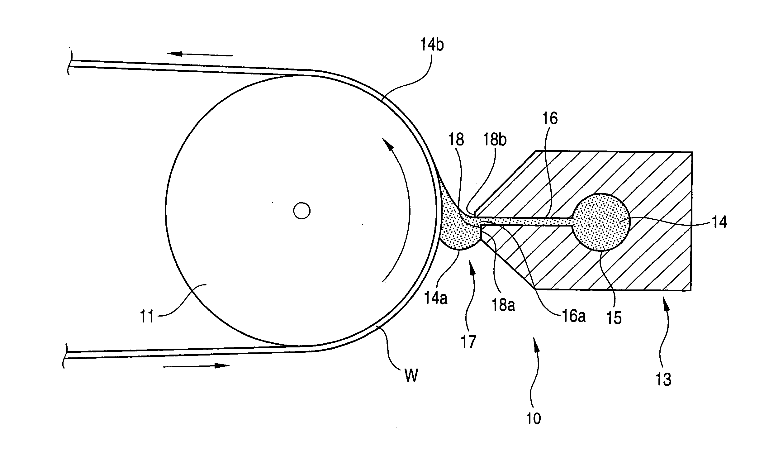
A method for coating anti-reflection films by die coating has been proposed as a way of measuring materials before the operation, but this method was also found difficult to secure a stable film thickness due to marked irregularities of a coated thickness which developed vertically and horizontally in relation to the transporting direction of a support in a case where coating on a thin layer like an anti-reflection layer.
These irregularities of coated thickness of the anti-reflection layer are detected by visual inspection as non-uniform color when the layer is used in an image display device, posing serious problems on quality.

Method used


Image

  • Method For Manufacturing An Optical Film, Apparatus For Manufacturing The Same Optical Film, Polarizing Plate And Image Display Device
  • Method For Manufacturing An Optical Film, Apparatus For Manufacturing The Same Optical Film, Polarizing Plate And Image Display Device
  • Method For Manufacturing An Optical Film, Apparatus For Manufacturing The Same Optical Film, Polarizing Plate And Image Display Device

Examples


examples

Examples of Layer Forming Method (I)

Example: A-1

[0508] Hereinafter, the present invention will be explained in detail by referring to the following examples. However, it shall be construed that the present invention is not limited to these examples. Parts are based on mass in present examples.

(Preparation of Coating Solution for Hard-Coat Layer)

[0509] The following compositions were put into a mixing tank and agitated to give a coating solution for hard-coat layer.

[0510] Polyglycidyl methacrylate of mass-average molecular weight 15000, 270.0 parts by mass; methyl ethyl ketone, 730.0 parts by mass; cyclohexanone 500.0 parts by mass and photo polymerization initiator (Irgacure 184, manufactured by Ciba Speciality Chemicals), 50.0 parts by mass were added to trimethyrolpropane triacrylate (Viscoat No. 295 (Osaka Organic Chemical Industry, Ltd.), 750.0 parts by weight and agitated. The resultant was filtered through a polypropylene filter with a pore diameter of 0.4 μm to prepare ...

example-2

[0539] Samples No. 113 through 118 were prepared in the same manner as in the samples No. 102, 103, 104, 105, 108 and 109 of Example A-1, except that they were passed through a nitrogen-replaced zone prior to a UV irradiation zone, and evaluated similarly. The preparing method of samples No. 119 and 120 were different from that of the sample No. 105 of Example A-1 only in that they were passed through a nitrogen-replaced zone prior to a UV irradiation zone. Where a film was to be heated after UV irradiation, heating was conducted by allowing the film after irradiation to contact with a rotating metal roll into which warm water or pressurized steam was passed.

TABLE 3Conditions of nitrogenreplacement zoneprior to UV irradiationConditions of UV irradiationSampleOxygen concentrationPassageOxygen concentrationIrradianceFilmHeatingNo.(% by vol)time (sec)(% by vol)(mJ / cm2)Heatingtemperature (° C.)time (sec)Remarks102——21600Not heated25—Comparativeexample103——0.1600Heated3030Presentinvent...

example-3

[0542] Similar evaluation was made for Example A-3 in which P-1 and P-2 described in the text (equivalent mass replacement) were used respectively in place of fluorine-containing polymers used in the low refractive layer of Example A-1 to 2 to obtain similar effects as those found in Example A-1 to 2.


PUM

PropertyMeasurementUnit
Temperatureaaaaaaaaaa
Lengthaaaaaaaaaa

Abstract

A method for manufacturing an optical film comprising a transparent substrate and at least one functional layer on or above the transparent substrate, wherein said at least one functional layer to be laminated on the transparent substrate is formed by a layer-forming method comprising the following steps (1) and (2): (1) step of applying a coated layer on the transparent substrate, and (2) step of curing the coated layer by irradiating ionizing radiation in an oxygen environment in which the oxygen concentration is lower than an atmospheric oxygen concentration.

Description

TECHNICAL FIELD [0001] The present invention relates to a method for manufacturing an optical film excellent in abrasion / scratch resistance (particularly anti-reflection film excellent in abrasion / scratch resistance at low reflectance), apparatus for manufacturing the same and an optical film obtained by said method. The invention also relates to a polarizing plate and an image display device equipped with said optical film. BACKGROUND ART [0002] Various functional optical films such as polarizing plate-protective film, phase contrast plate, reflection plate, viewing angle widening film, optically compensated film, anti-glare film, brightness improved film, color correction filter, color separation film, ultraviolet ray- or infrared ray-protected film, antistatic film and anti-reflection film have been used in display devices such as a cathode ray tube (CRT) display device, plasma display panel (PDP), electroluminescence display (ELD) and liquid crystal display (LCD). These films re...

Claims


Application Information

Patent Timeline
IPC IPC(8): H01L27/10
CPCB05C5/0254G02B5/3025B05C9/14B05D3/0486B05D3/067B05D3/068B05D5/083B05D7/04B05D2201/02B05D2252/02B29C43/222B29C55/06B29D11/0073B29K2001/00B29K2001/12B29K2029/04B29K2995/0034B29L2007/008B29L2011/00G02B1/111B05C9/06
Inventor OHTANI, SHIGEAKISATOH, MAKOTOMAEKAWA, TOSHIHIKOSUZUKI, MAYUMIFUKUSHIGE, YUUICHI
Owner FUJIFILM CORP
Learn More