
Oxide sintered body, manufacturing method therefor, manufacturing method for transparent conductive film using the same, and resultant transparent conductive film

a manufacturing method and technology of oxidized sintered body, which are applied in the direction of conductive materials, diaphragms, metallic material coating processes, etc., can solve the problems of difficult to manufacture transparent conductive films, non-indium-based materials, and difficulty in maintaining small variation of oxygen gas amount in atmosphere gas, etc., to achieve excellent chemical resistance, high productivity, and stable characteristics

Inactive Publication Date: 2007-09-20
SUMITOMO METAL MINING CO LTD
View PDF6 Cites 39 Cited by
  • Summary
  • Abstract
  • Description
  • Claims
  • Application Information

AI Technical Summary

Benefits of technology

The present invention provides an oxide sintered body that is stable and can be formed into a film with high-speed, without arcing or cracking, even under high DC power. The oxide sintered body contains a tin oxide crystal phase and at least one kind of zinc stannate compound phase. The invention also provides a method for manufacturing the oxide sintered body and an oxide transparent conductive film using the same. The oxide sintered body is resistant to chemicals and can be used in various applications such as chemical resistance, high-speed film formation, and high-temperature sintering.

Problems solved by technology

A method using an alloy target requires increased oxygen gas flow, because all oxygen in the resultant transparent conductive film is fed from oxygen gas in atmosphere; resulting in difficulty in maintaining small variation of oxygen gas amount in atmosphere gas.
This method makes difficult to manufacture a transparent conductive film having consistent thickness and consistent characteristics, because film formation speed or characteristics (resistivity and transmittance) of the resultant film extremely largely depends on oxygen gas amount introduced into the atmosphere (see “Transparent conductive film technology”, Japan Society for the Promotion of Science, published by Ohmsha, Ltd., page 173, published in 1999).
By the way, an indium oxide-based material such as ITO or the like is widely used to obtain a transparent conductive film as described above, however, a non-indium-based material is required, because an indium metal is a rare metal on the earth, and it has toxicity and affects badly to environment or a human body.
A transparent conductive film made of a zinc oxide-based material is industrially manufactured by a sputtering method, however, it has a defect of poor chemical resistance (alkali resistance and acid resistance).
In addition, a transparent conductive film made of a tin oxide-based material, although excellent in chemical resistance, has defect of difficulty in manufacturing by a sputtering method, because of difficulty in manufacturing a tin oxide-based sintered body target having high density and durability.
However, because the film is formed by high frequency sputtering using a powder-like target, such a target is not capable of obtaining an excellent transparent conductive film in a DC sputtering method.
However, this transparent film of mixed oxides of zinc and tin is formed by a reactive sputtering method using a zinc-tin-based alloy target, and has poor characteristics reproducibility of the resultant film.
In general, a manufacturing method for a metal oxide thin film by reactive sputtering using a metal target is more likely to provide significant variation of film composition and film characteristics, and reduce yield.
However, there is no practical use of the oxide sintered body for a sputtering target, or the oxide sintered body for an ion plating tablet, to provide high-speed film formation of a Zn—Sn—O-based thin film; namely, a conventional oxide sintered body generates a problem of arcing generation or the like by charging high DC power, therefore the selection here is limited only to film formation by charging low DC power, or by a high frequency sputtering method which provides low-speed film formation, and thus high productivity cannot be attained.
In addition, generation of arcing during film formation causes generation of particles and may also reduce product yield.
In addition, continued arcing generation not only inhibits film formation itself but also inhibits manufacturing of a high quality film because of generation of damage in a film itself.
Reactive sputtering using a zinc-tin-based alloy target, described in JP-A-2-145458, is more likely to attain high-speed film formation of a metal oxide thin film made of zinc and tin, however, stable manufacturing is inhibited because of large variation of film composition or conductivity or transmittance.

Method used


Image

  • Oxide sintered body, manufacturing method therefor, manufacturing method for transparent conductive film using the same, and resultant transparent conductive film

Examples


examples

[0087] The present invention will specifically be explained below with reference to Examples, however, the present invention should not be limited thereto. In addition, the resultant oxide sintered body and transparent conductive film were evaluated by the following methods:

(Evaluation of the Oxide Sintered Body)

[0088] Resistivity of the resultant oxide sintered body was measured on the polished surface by a four-pin probe method.

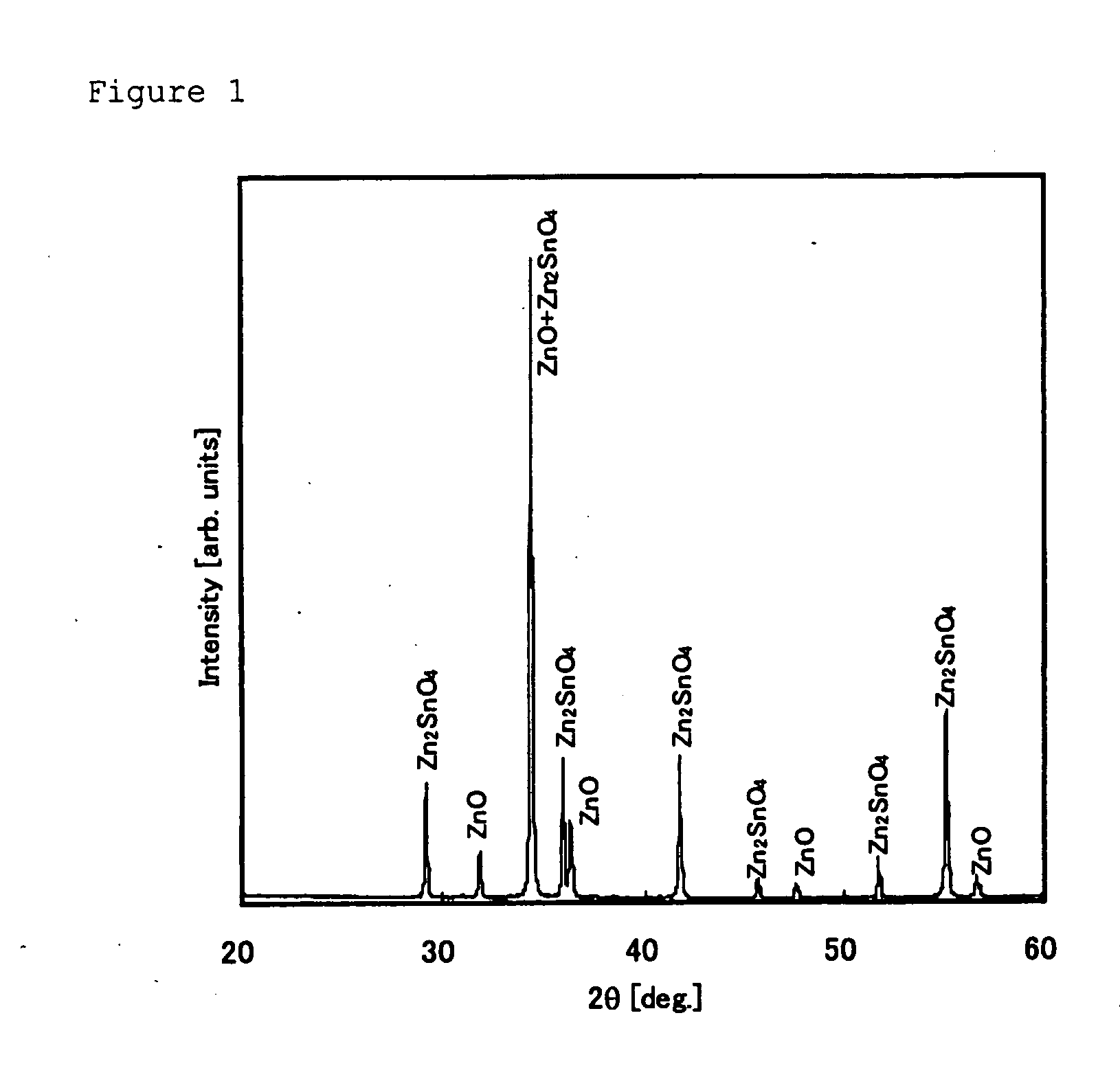
[0089] On the other hand, generated phases were identified by powder X-ray diffraction measurement of the resultant oxide sintered body; diffraction peaks originating from a tin oxide phase of a rutile structure, a zinc stannate phase, ZnSnO3, described by the JCPDS card, 52-1381, and zinc oxide were observed. In addition, by local composition analysis by EPMA, whether or not tin was dissolved, as a sold solution, in a zinc oxide crystal phase was determined. Further, composition of the oxide sintered body was analyzed using an ICP emission spectroscopy...

examples 1 to 7

Manufacturing of the Oxide Sintered Body

[0091] Firstly, ZnO powder with an average grain size of equal to or smaller than 1 μm, and SnO2 powder with an average grain size of equal to or smaller than 1 μm were used as raw material powder, formulated at an atomic number ratio, Sn / (Zn+Sn), of 0.25, charged into a resin pot together with water, and mixed by a wet process ball mill. In this case, a hard ball made of ZrO2 was used, and mixing time was set to 18 hours. After mixing, slurry was taken out and subjected to filtering, drying and granulation.

[0092] The granule was subjected to compacting by pressurization under a pressure of 3 tons / cm2 by a cold hydrostatic press.

[0093] Then, the resultant compact was sintered under atmosphere introduced with oxygen into the atmosphere of the sintering furnace at a speed of 5 L / min. per 0.1 m3 of inner furnace volume (oxygen concentration of the calcination atmosphere to be 55%) at a temperature of 1450° C. for 20 hours. In this case, the t...

example 8

[0100] The oxide sintered body was prepared in the same way as in Example 1, except that the atomic number ratio, Sn / (Zn+Sn), was changed to 0.23, and the oxygen amount in the calcination atmosphere was changed to 40%. End parts of the resultant oxide sintered body was subjected to powder X-ray diffraction measurement; as for the oxide sintered body having a atomic number ratio, Sn / (Zn+Sn), of 0.23, diffraction peaks originating from the zinc oxide crystal phase of a wurtzite type structure, and the zinc stannate phase, Zn2SnO4, described by the JCPDS card, No. 24-1470 were observed; however, a diffraction peak originating from tin oxide such as SnO2 or SnO or the like was not observed. Local composition analysis of this sintered body by EPMA showed that tin was dissolved, as a sold solution, in the zinc oxide phase. Composition analysis of the resultant oxide sintered body, by ICP emission spectroscopy, showed that the composition was the same as that in raw material powder in form...


PUM

PropertyMeasurementUnit
atomic number ratioaaaaaaaaaa
resistivityaaaaaaaaaa

Abstract

The present invention relates to the oxide sintered body substantially containing zinc, tin and oxygen, useful as a target, which can be sputtered under charging of high DC power, without generation of arcing or crack, and a manufacturing method for an oxide transparent conductive film formable in high-speed, and the oxide transparent conductive film excellent in chemical resistance. The oxide sintered body substantially containing zinc, tin and oxygen; containing tin at an atomic number ratio, Sn / (Zn+Sn), of 0.23 to 0.50, and being composed mainly of a zinc oxide phase and at least one kind of zinc stannate compound phase, or being composed of at least one kind of zinc stannate compound phase; provided by a method for manufacturing the oxide sintered body by formulating an aqueous solvent to raw material powder containing powder of a zinc stannate compound, or mixed powder of tin oxide powder and zinc oxide powder, and after mixing the resulting slurry for equal to longer than 15 hours, by subjecting the slurry to solid-liquid separation, drying and granulation, and subsequently compacting by charging the granule into a mold, followed by sintering the resultant compact under sintering atmosphere at 1300 to 1500° C. for equal to or longer than 15 hours.

Description

BACKGROUND OF THE INVENTION [0001] 1. Field of the Invention [0002] The present invention relates to the oxide sintered body, a manufacturing method therefor, a manufacturing method for transparent conductive film using the same, and the resultant transparent conductive film, and more specifically the present invention relates to the oxide sintered body substantially containing zinc, tin and oxygen, useful as a target, which can be sputtered under charging of high DC power, and a manufacturing method for an oxide transparent conductive film formable in high-speed, and the oxide transparent conductive film excellent in chemical resistance. [0003] 2. Description of the Prior Art [0004] A transparent conductive film is widely used not only as electrodes of solar batteries or liquid crystalline display elements and other various light-sensitive elements, but also as heat reflecting films for automotive windows or construction applications, antistatic films, or antifogging transparent he...

Claims


Application Information

Patent Timeline
Patent Type & Authority Applications(United States)
IPC IPC(8): C23C14/00C23C14/32
CPCC04B35/453H01B1/08C04B35/6261C04B2235/3217C04B2235/3232C04B2235/3251C04B2235/3256C04B2235/3258C04B2235/3284C04B2235/3286C04B2235/3293C04B2235/3294C04B2235/5436C04B2235/5445C04B2235/6562C04B2235/6565C04B2235/6567C04B2235/6585C04B2235/6586C04B2235/664C04B2235/80C04B35/457
Inventor ABE, YOSHIYUKINAKAYAMA, TOKUYUKIOHARA, GOWAKE, RIICHIRO
Owner SUMITOMO METAL MINING CO LTD
Learn More