System and Method for Direct Digitization of NMR Signals

a technology of direct digitization and imaging data, applied in the field of magnetic resonance imaging systems, can solve the problems of inability to harness the capabilities of mri systems to yield higher quality images, inability to readily utilize mri systems without redesigning, and extreme rigidity, and achieve the effect of being ready for mass production

Inactive Publication Date: 2007-09-27
THE MEDICAL COLLEGE OF WISCONSIN INC
View PDF11 Cites 17 Cited by
  • Summary
  • Abstract
  • Description
  • Claims
  • Application Information

AI Technical Summary

Benefits of technology

[0014]The present invention overcomes the aforementioned drawbacks by providing a system and method for utilizing receiver components in MRI receiver systems that are capable of achieving direct detection/digitization of received nuclear magnetic resonance (NMR) signals. As will be described, the present invention, though described with respect to NMR signals, is also capable of receiving and processing other signals, such as electron spin resonance (ESR) signals. F...

Problems solved by technology

Since the received signal is at or around the Larmor frequency and these hardware-based receive systems cannot provide adequate sampling at such high frequencies, this high frequency signal is down-converted in a two-step process by a down converter that first mixes the imaging signal with the carrier signal and then mixes the resulting difference signal with a reference signal.
While these hardware-based systems yield suitable results, they are extremely rigid since they are specifically designed and tailored for a particular MRI system.
In this regard, although a wide variety of components, such as analog-to-digital converters, are produced as commodity (i.e., low-cost and/or mass-produced) components for use in mass-market devices (e.g., cellular phones and the like), these components cannot be readily utilized in MRI systems without redesigning or reconfiguring the hardware of the receiver system to accommodate the specific functionality of a given commodity component.
Furthermore, as various hardware designs and components attain higher bandwidth and dynamic range, th...

Method used


Image

  • System and Method for Direct Digitization of NMR Signals
  • System and Method for Direct Digitization of NMR Signals
  • System and Method for Direct Digitization of NMR Signals

Examples


Embodiment Construction

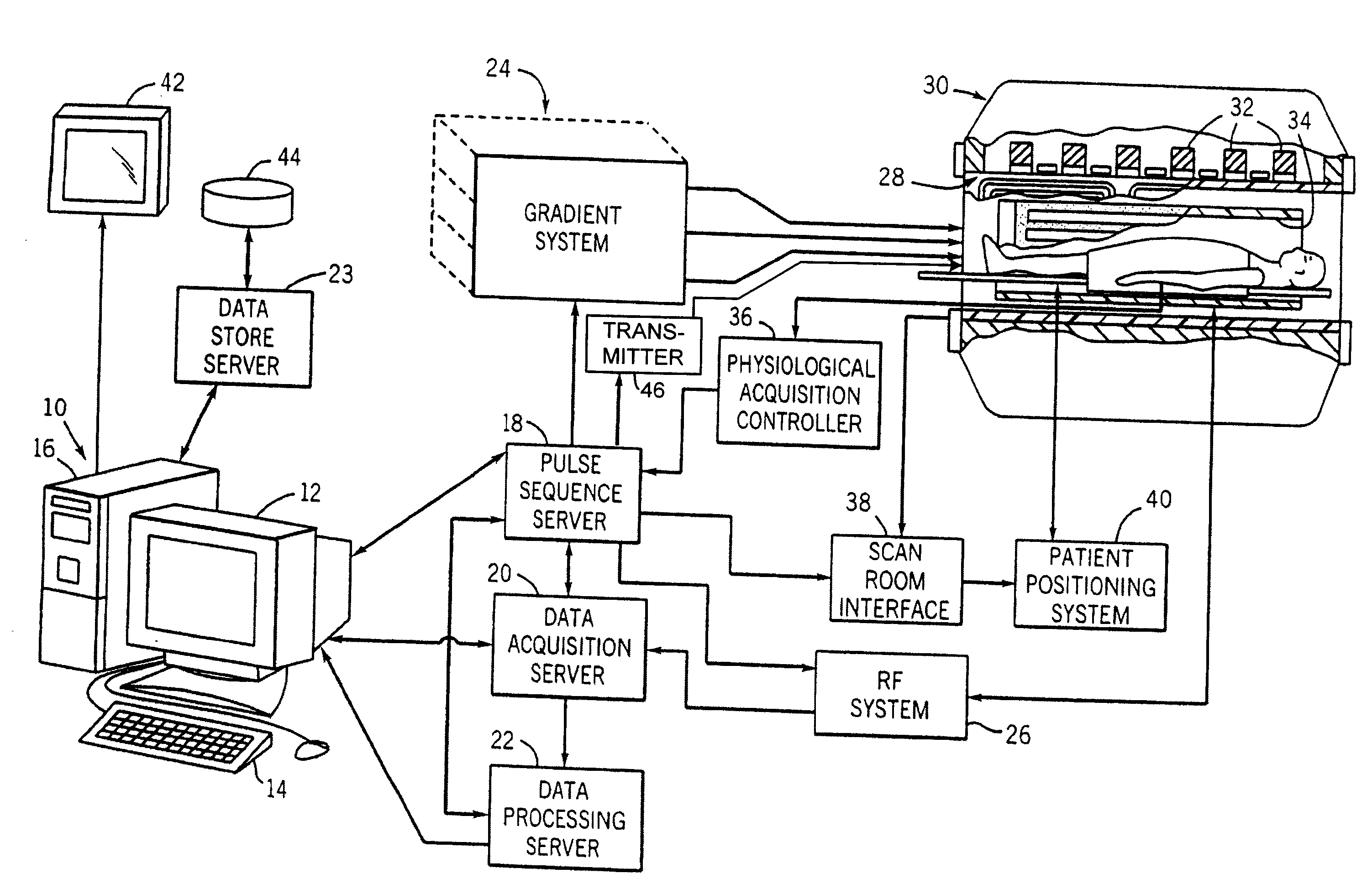
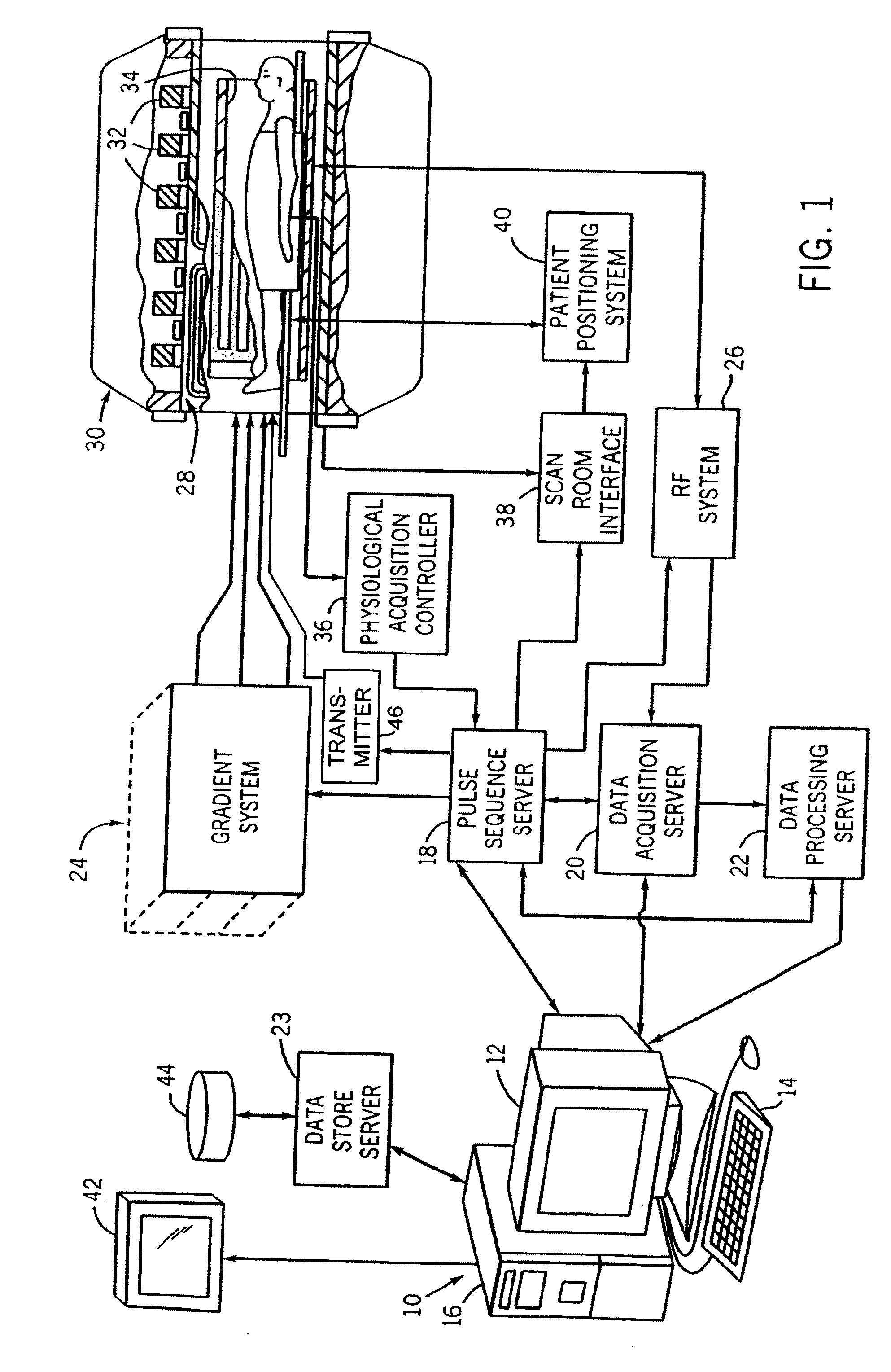
[0025]Referring to FIG. 1, an MRI system includes a workstation 10 having a display 12 and a keyboard 14. The workstation 10 includes a processor 16 which is a commercially available programmable machine running a commercially available operating system. The workstation 10 provides the operator interface which enables scan prescriptions to be entered into the MRI system.

[0026]The workstation 10 is coupled to four servers: a pulse sequence server 18; a data acquisition server 20; a data processing server 22; and a data store server 23. It is contemplated that the functionality of the data store server 23 may be performed by the workstation processor 16 and associated disc drive interface circuitry or may be a stand-alone computer system. In any case, functionalities of the remaining three servers 18, 20, and 22 are performed by separate processors mounted in a single enclosure and interconnected using a backplane bus. The pulse sequence server 18 employs a commercially available micr...


PUM


Abstract

A magnetic resonance imaging (MRI) system includes a transmitter that produces an RF excitation pulse that is applied to a subject positioned in the MRI system to induce emission of at least one of an NMR signal and an ESR signal therefrom, and that produces a reference signal indicative of the phase of the RF excitation pulse. A first analog-to digital converter has an input for receiving the reference signal that is synchronous with the RF excitation pulse. One or more additional analog-to-digital converters/processors have inputs for receiving the at least one of NMR signals and ESR signals produced by a subject placed in the MRI system and produce one or more complex digital signal therefrom. A normalizer is connected to receive and normalize the digital reference signal and a mixer is connected to receive the normalized digital reference signal and the digital signal. Accordingly, the mixer is operable to multiply the normalized complex digital reference signal with the complex digital signal.

Description

CROSS-REFERENCE TO RELATED APPLICATIONS[0001]This application is based on provisional application 60 / 743,739 filed Mar. 24, 2006 and entitled “System and Method for Direct Digitization of NMR Signals” and claims the benefit thereof.STATEMENT REGARDING FEDERALLY SPONSORED RESEARCH[0002]--BACKGROUND OF THE INVENTION[0003]The present invention relates generally to magnetic resonance imaging (MRI) systems and, more particularly, to a system and method for receiving and directly digitizing imaging data signals. The invention is capable of utilizing commodity analog-to-digital (A / D) converters and adaptable software-processing algorithms to improve image quality while reducing manufacturing costs.[0004]When a substance such as human tissue is subjected to a uniform magnetic field (polarizing field B0), the individual magnetic moments of the spins in the tissue attempt to align with this polarizing field, but precess about it in random order at their characteristic Larmor frequency. If the...

Claims


Application Information

Patent Timeline
IPC IPC(8): G01N24/00G01V3/00
CPCY10T436/24G01R33/3621
Inventor JESMANOWICZ, ANDRZEJ
Owner THE MEDICAL COLLEGE OF WISCONSIN INC
Why Eureka
Try Eureka