
Novel membrane electrode assembly and its manufacturing process

a technology of membrane electrodes and manufacturing processes, applied in the manufacture of final products, conductive materials, synthetic resin layered products, etc., can solve the problems of high temperature, damage to membranes, and fine pores in catalyst layers that could be crushed, so as to reduce electric resistance, proton resistance and fuel crossover, the effect of increasing mechanical strength

Inactive Publication Date: 2007-11-29
SHANGHAI HORIZON FUEL CELL TECH
View PDF2 Cites 64 Cited by
  • Summary
  • Abstract
  • Description
  • Claims
  • Application Information

AI Technical Summary

Benefits of technology

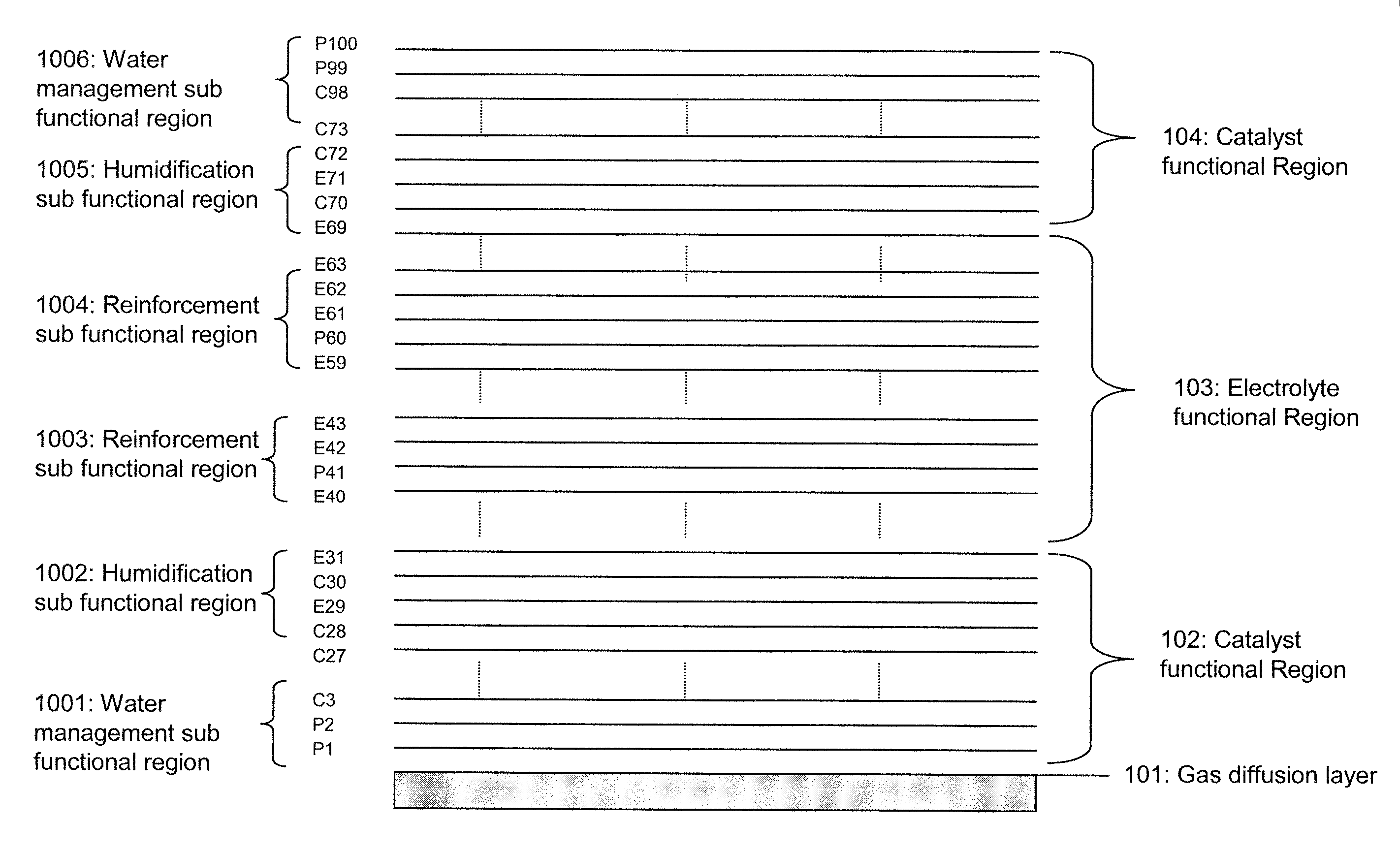
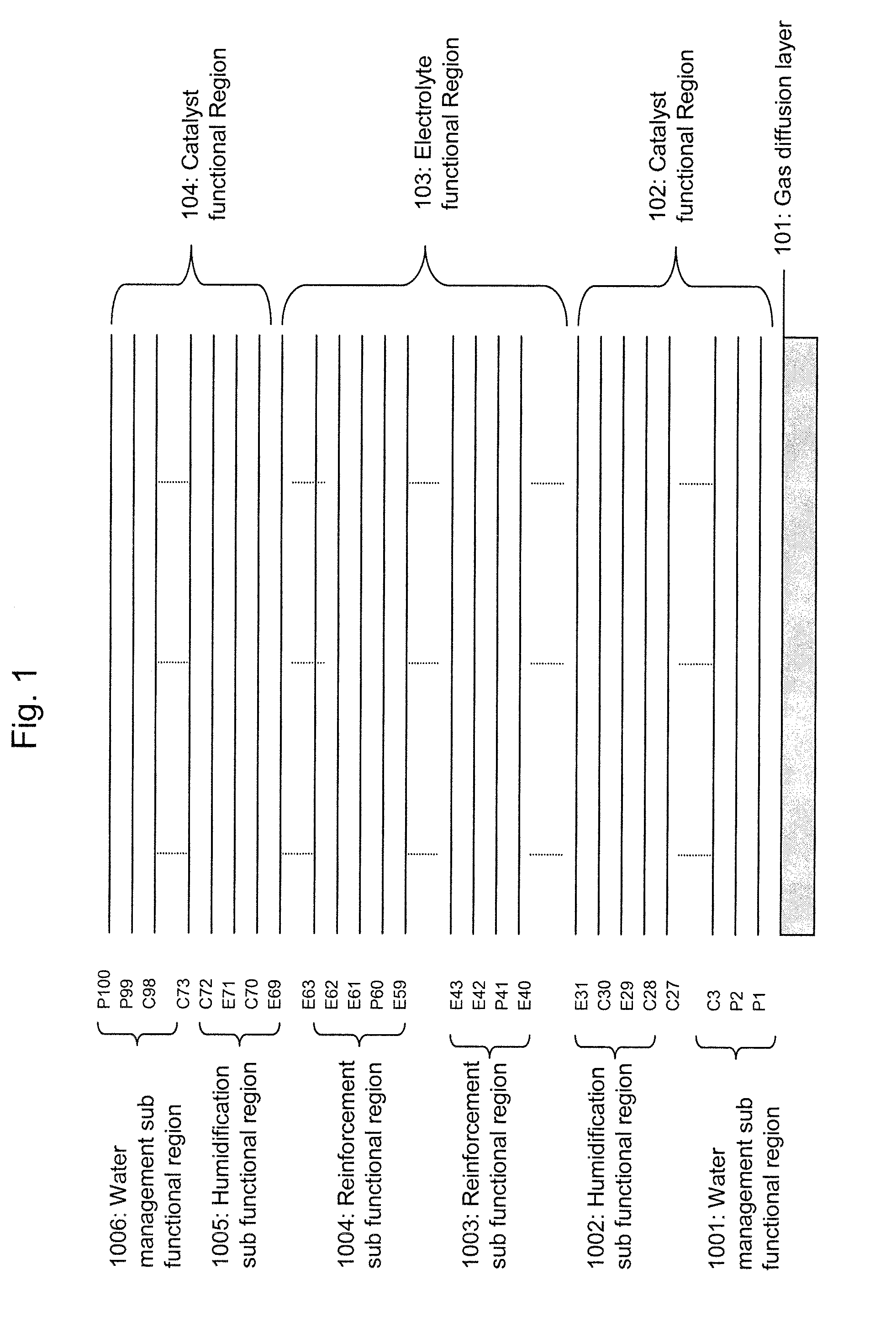
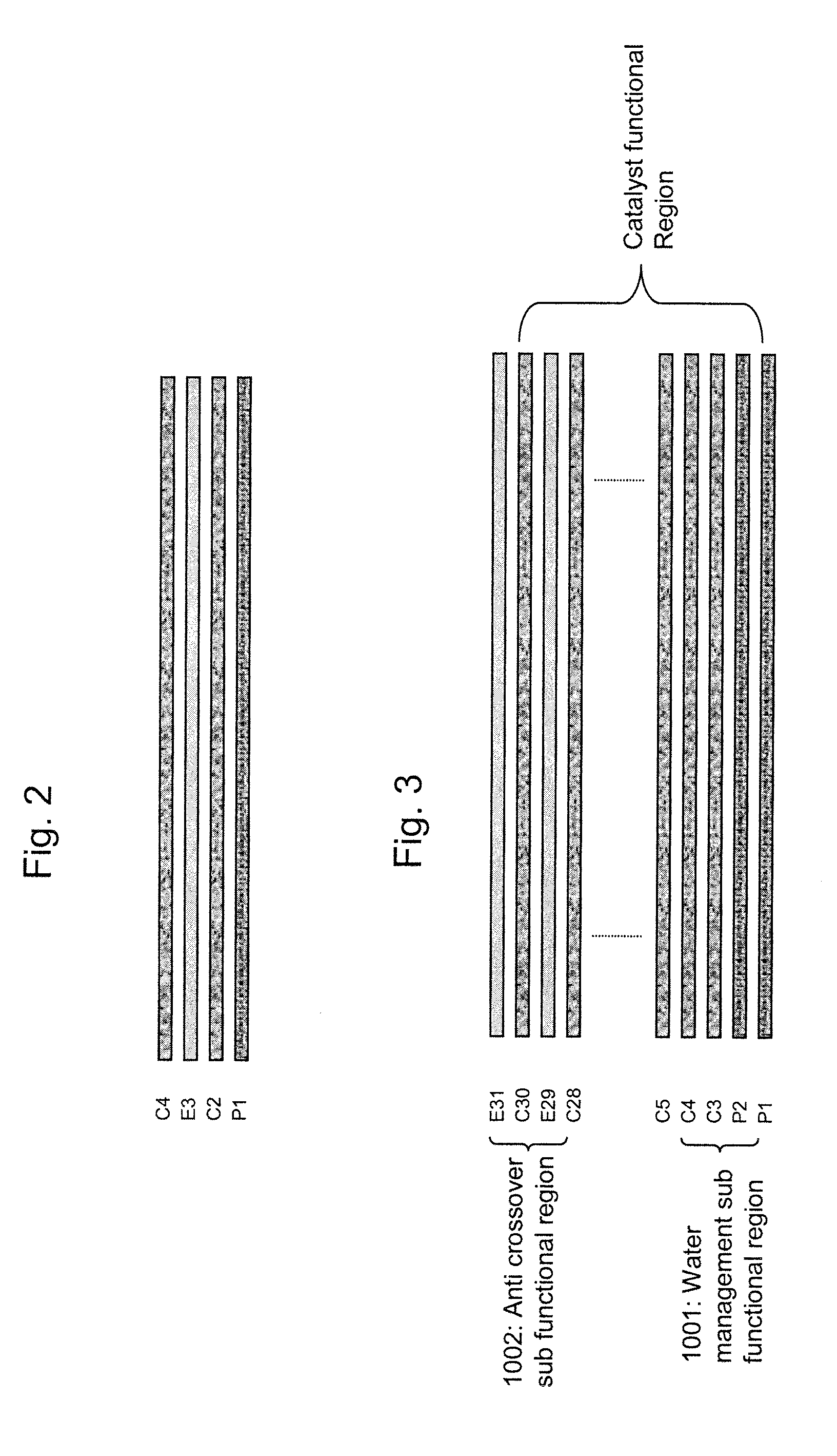
[0013] Aspects of the present invention relate to a novel MEA having 4 to 1000 layers in three basic types. The combinations of the three types of layers form different functional regions in an MEA to reduce electric resistance, proton resistance and fuel crossover, and to increase the mechanical strength, of the MEA. It is characterized that the MEA has multiple main functional regions and sub functional regions, and each main functional region and sub functional region are formed by the combination of 2 to 3 types of layers. It is further characterized that the MEA is prepared with a novel ultrasonic deposition process. The MEA is suitable for applications such as hydrogen fuel cells, methanol fuel cells and electrolyzers.

Problems solved by technology

Since hot lamination is often required in conventional MEA construction, fine pores in the catalyst layers could be crushed and the membrane might be damaged under high pressure and high temperature conditions.
For the construction of fuel cells with conventional three layer and five layer MEAs, a high clamping force is required to reduce contact resistance, which may also crush the fine pores in the catalyst layers and may damage the membrane during the assembly of fuel cells.
However, it has three disadvantages, 1, it uses conventional “thick film” coating methods to coat each layers and it is difficult to coat layers with thickness from less than one micron precisely; 2, the coating process and the drying / curing process are conducted in a sequential manner, which increase production time and causes the difficulty to control the physical features of each layer; 3, as pointed out in the patent, the fine pores of the first catalyst layer are impregnated by the ion-exchange resin, causing power losses if the first catalyst layer is used as the cathode layer.
In addition, all the above noted MEA construction methods have limitations in addressing the issue of catalyst utilization and the gas, electron and proton three phase interface optimization.
Great loss of precious catalyst material often occurs in conventional MEA structure since catalysts do not participate in the electrochemical reaction in the areas where there're no sufficient proton paths and electron paths.
It is difficult to optimize the three phase interface with construction methods disclosed in prior art.
Furthermore, all the above noted MEA construction methods could not solve the problems associated with the proton exchange membrane.
Currently, the most commonly used fluorine-containing membranes have various short comings such as, 1) high fuel crossover and low mechanical strength especially when the membrane is thinner than 50 microns; 2) insufficient chemical resistance in the presence of some liquid fuels; 3), low proton conductivity, poor chemical stability and poor mechanical properties at high temperature.
With the conventional MEA construction methods, it is difficult to use ultra-thin membranes to increase proton conductivity since the membrane requires high mechanical strength to sustain the high pressure during the construction process.
In addition, the above noted methods all use thick film coating methods such as roller coating, bar coating, spin coating, screen printing, air spray coating, brush coating, etc., which is suitable for coating layers with thickness from hundreds of microns to millimeters, however, is not suitable for coating layers with thickness from less than 1 micron to less than ten microns.
The above prior arts could not address the catalyst layer location issue well and the manufacturing methods disclosed are multi-steps and complicated.
In addition, the art disclosed in EP 0631337 has poor utilization of catalyst and may cause short circuit of the MEA.
However, few hybrid membranes could have higher proton exchange conductivity than Nafion (TM, Dupont) membrane under well humidified and low temperature operating conditions.
Also, the preparation of such membrane often involves multiple steps and the manufacturing processes are complicated.
However, the porous films used in conventional reinforced membrane reduce proton conductivity and an un-reinforced proton exchange membrane typically has higher proton conductivity than a conventional porous film reinforced membrane of same material and same thickness.

Method used


Image

  • Novel membrane electrode assembly and its manufacturing process
  • Novel membrane electrode assembly and its manufacturing process
  • Novel membrane electrode assembly and its manufacturing process

Examples


example 1

[0086] The solution for the polymer layer is atomized with an ultrasonic nozzle at a frequency of 120 KHz and sprayed at a flow rate of 0.5 ml / minute to a heated carbon fiber paper with a surface temperature of 150° C. The droplets dried immediately and multiple coatings are applied, until the dried polymer layers reach 0.4 mg / cm2. The polymer layer coated carbon fiber paper is placed in an oven with a temperature of 370° C. for 20 minutes. It is further placed on a hot plate and heated to 140 C. Then electrolyte solution 1 is atomized and sprayed to the polymer layer coated carbon fiber paper until 0.1 mg / cm2 of electrolyte is coated. Multiple catalyst layers are further sprayed to the carbon fiber paper until a Pt loading of 0.2 mg / cm2 in the new catalyst layers is reached. Multiple electrolyte layers of electrolyte solution 1 are further coated until 5 mg / cm2 of new electrolyte is coated. Multiple catalyst layers are further coated until additional 0.4 mg / cm2 of Pt loading is rea...

example 2

[0087] A 3 micron thick porous PTFE film is placed on a carbon fiber paper, catalyst layers are ultrasonically deposited to the porous PTFE film until the Pt loading of 0.4 mg / cm2 is reached in the first catalyst functional region. Electrolyte layers of electrolyte solution 1 are further ultrasonically deposited to the catalyst functional region until the loading of electrolyte reaches 4 mg / cm2. Catalyst layers are further ultrasonically deposited to the electrolyte functional region until the Pt loading reaches 0.01 mg / cm2. Electrolyte layers then are further deposited until the total electrolyte loading reaches 5 mg / cm2. Finally, catalyst layers for the second catalyst functional region are ultrasonically deposited to the electrolyte functional region until the Pt loading for the second catalyst functional region reaches 0.4 mg / cm2. The MEA then is further heat treated in an oven at 150° C. for 10 minutes. During the entire coating process, the ultrasonic nozzle's frequency is set...

example 3

[0088] A piece of carbon fiber paper is placed on a heated hot plate. The solution for the catalyst layers is atomized and sprayed to the heated carbon fiber paper. The droplets dried immediately and multiple coatings are applied, until the Pt loading of the first catalyst functional region reaches 0.2 mg / cm2. Then the electrolyte layers of solution 1 are atomized and sprayed to the heated carbon fiber paper until the electrolyte functional region reaches 3 mg / cm2 of electrolyte loading. Multiple catalyst layers are further sprayed to the electrolyte layers until the second catalyst region reaches 0.4 mg / cm2 of Pt loading. The MEA is further cut into multiple single cell size MEA (3.4 cm*10 cm) and a smaller single cell size carbon fiber paper (3 cm*9.6 cm) is placed in the middle of the single cell MEA to be further used to assemble fuel cell stacks. The 0.2 mg / cm2 pt loading catalyst functional region can be used as the anode catalyst layers. During the entire coating process, the...


PUM

PropertyMeasurementUnit
Fractionaaaaaaaaaa
Fractionaaaaaaaaaa
Fractionaaaaaaaaaa

Abstract

A membrane electrode assembly including a gas diffusion layer and a layered structure made up of from 4 to 1000 layers including layers of a first type and layers of a second type, wherein the layers of the first type are electrolyte layers and the layers of the second type are catalyst layers, the layered structure having one or more catalyst functional regions, each made up of layers of the first and second types, and one or more electrolyte functional regions, each made up of layers of the first and second types.

Description

[0001] This application claims the benefit of U.S. Provisional Application No. 60 / 799,268, filed May 10, 2006, all of which is incorporated herein by reference.TECHNICAL FIELD [0002] This invention generally relates to membrane electrode assemblies. BACKGROUND [0003] Polymer electrolyte membrane fuel cells are electrochemical devices that convert chemical energy of hydrogen into electrical energy without combustion. They have high potential to offer an environmentally friendly, high-energy density, efficient, and renewable power source for various applications from portable devices to vehicles and stationary power plants. [0004] Membrane electrode assembly (MEA) is the heart of a polymer electrolyte fuel cell and an MEA typically is comprised of a membrane, anode catalyst layer, cathode catalyst layer, anode diffusion layer and cathode diffusion layer. A three layer MEA usually has a catalyst coated to both sides of a central membrane and a five layer MEA further includes two diffus...

Claims


Application Information

Patent Timeline
IPC IPC(8): H01M4/94H01M4/96H01M4/88B05D5/12
CPCB32B5/16B32B2457/18B32B27/322B32B2255/28B32B2262/106B32B5/18B32B5/24B32B9/04B32B27/06B32B27/12B32B27/30H01B1/122H01M4/8605H01M4/8642H01M4/8657H01M4/8814H01M4/8817H01M4/8825H01M4/8882H01M4/92H01M8/04119H01M8/04261H01M8/1004H01M8/1023H01M8/1039H01M8/1046H01M8/1053H01M8/1081H01M2300/0082H01M2300/0094Y02E60/523B32B15/02H01M8/04197Y02P70/50Y02E60/50
Inventor GU, ZHIJUNGU, YIXIONG
Owner SHANGHAI HORIZON FUEL CELL TECH
Learn More