Processing Method For Organic Crystal, Processing Device For Organic Crystal, And Observing Device For Organic Crystal

a processing method and organic crystal technology, applied in the direction of material analysis using wave/particle radiation, crystal growth process, gel state, etc., can solve the problems of work surface not being as expected in some instances, work surface damage by heat, and object of work must be first returned to an ordinary temperature, etc., to achieve the effect of reducing the absorption of short-pulse laser light by liquid, high degree of precision and increasing working efficiency

Active Publication Date: 2007-12-06
NIKON CORP +6
View PDF0 Cites 11 Cited by
  • Summary
  • Abstract
  • Description
  • Claims
  • Application Information

AI Technical Summary

Benefits of technology

[0014] If this is done, even in cases where a liquid adheres to the surface of an organic crystal, especially even in cases where an organic crystal is worked while being held in a liquid, the movement of the liquid caused by irradiation with short-pulse laser light is suppressed by virtue of this liquid also being cooled and frozen, so that working can be performed with a high degree of precision. Furthermore, even in cases where the adhering liquid absorbs the irradiating laser light, there is less possibility of the liquid coming from another portion into the portion where the liquid is removed. Therefore, the absorption of the short-pulse laser light by the liquid is reduced, so that the working efficiency is increased.
[0015] Moreover, for example, in cases where some type of observation of an organic crystal is performed in a state in which this organic crystal is cooled to a low temperature, if working is performed while maintaining the temperature of the crystal in the vicinity of the temperature during observation, it becomes easier to repeat observation and working without subjecting this organic crystal to a temperature cycle between a low temperature and an ordinary temperature, which makes it possible to avoid damage to the organic crystal and an effect involving the alteration of the structure which accompanies a large temperature change.
[0016] In addition, in cases where the organic crystal consists of a material containing moisture, working in a low-temperature frozen state also makes it easier to avoid problems such as degeneration of the crystal caused by drying.
[0017] With regard to the laser light with which the object of working is irradiated, short-pulse laser light is desirable because heat accumulation effect on the object of working increases in working using continuous light. The short-pulse laser light refers to laser light having a pulse width and a pulse interval which are such that the object of working that is cooled to a low temperature does not undergo degeneration or fusion due to temperature elevation caused by the laser irradiation, and such that the substance holding the object of working is not deformed or does not generate any positional fluctuation due to temperature elevation caused by the laser irradiation.

Problems solved by technology

Specifically, in working by using a carbon dioxide gas laser or YAG laser, cleaving is performed by utilizing fusion caused by the generation of heat in laser light irradiated parts, and there is a problem in that the cleaved surface is damaged by heat.
However, the invention of the previous application is premised on working at ordinary temperatures, so that when X-ray crystal structure analysis is performed under low-temperature conditions, if working is required following cooling, this presents a problem in that the object of working must be first returned to an ordinary temperature.
Moreover, depending on the working method involved, the following problems are encountered.
Firstly, in cases where the object of working is to be worked in a state in which this object is held in a liquid or liquid film, the object of working may move during working, so that the worked surface may not be as expected in some instances.

Method used


Image

  • Processing Method For Organic Crystal, Processing Device For Organic Crystal, And Observing Device For Organic Crystal
  • Processing Method For Organic Crystal, Processing Device For Organic Crystal, And Observing Device For Organic Crystal
  • Processing Method For Organic Crystal, Processing Device For Organic Crystal, And Observing Device For Organic Crystal

Examples


embodiment 1

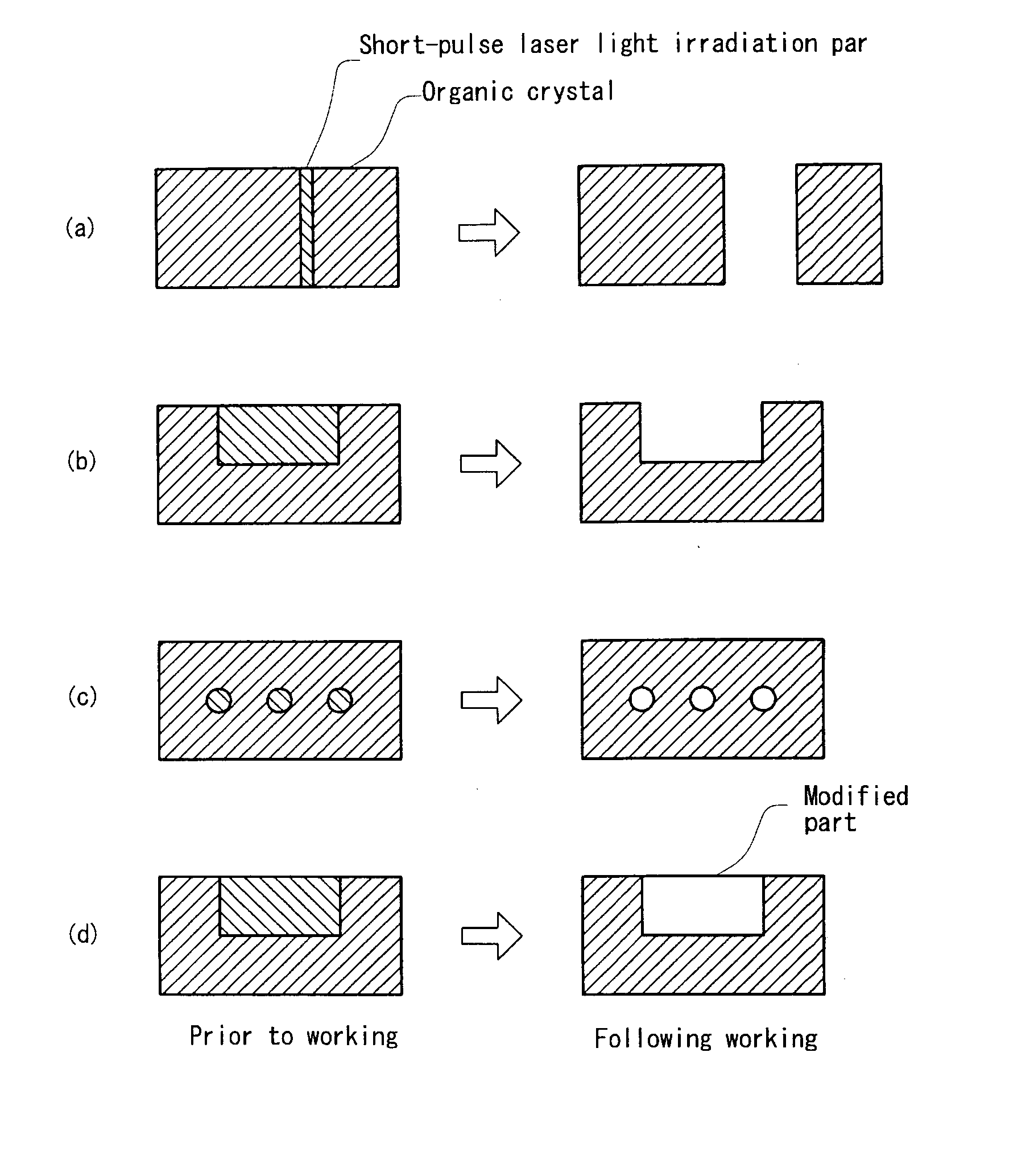
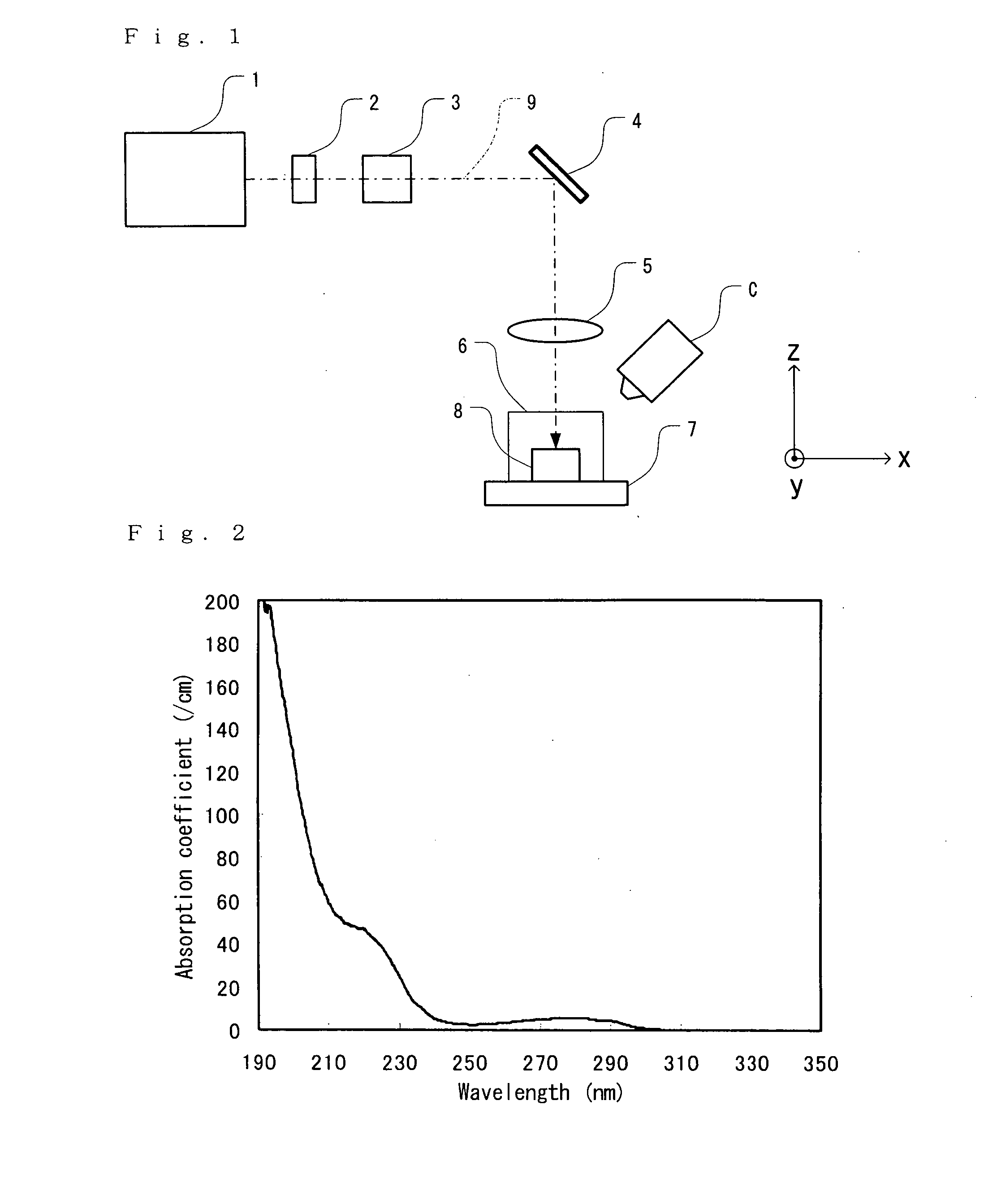
[0125] In order to investigate the basic characteristics of the working method of the present invention, a single crystal of phosphoenol pyruvic acid carboxylase (PEPC), which is a protein, was irradiated with ultraviolet short-pulse laser light having a wavelength of 193 nm using an apparatus of the type shown in FIG. 1; as a result, the crystal was cut in two.

[0126] The grown PEPC crystal was scooped up with a loop as shown in FIG. 4 (a) and held by surface tension. In this state, a low-temperature gas using nitrogen was caused to jet onto the PEPC crystal, the solution supporting the crystal, and the loop so that these were cooled to a low temperature. A photograph of the crystal prior to working is shown in FIG. 9 (a), and its model diagram is shown in FIG. 9 (b).

[0127] In a state in which a low-temperature gas was continuously caused to jet, irradiation was performed with approximately one million shots of laser light having a repetition frequency of 3.4 kHz, a pulse width of...

embodiment 2

[0129] A membrane protein single crystal (AcrB crystal) was irradiated with ultraviolet short-pulse laser light having a wavelength of 193 nm using an apparatus of the type shown in FIG. 1. As a result, the crystal was cut in two.

[0130] The grown AcrB crystal was scooped up with a loop as shown in FIG. 4 (a) and held by surface tension. In this state, a low-temperature gas using nitrogen was caused to jet onto the AcrB crystal, the solution supporting the crystal, and the loop so that these were cooled to a low temperature. A photograph of the crystal prior to working is shown in FIG. 10 (a), and its model diagram is shown in FIG. 10 (b).

[0131] In a state in which a low-temperature gas was continuously caused to jet, irradiation was performed with approximately one million shots of laser light having a repetition frequency of 3.4 kHz, a pulse width of approximately 1 ns, a spot diameter of 20 μm, and an energy density of 50 mJ / cm2 while moving the spot at 0.5 mm / sec, and the loop ...

embodiment 3

[0132] X-ray diffraction patterns were measured before and after the working of a protein single crystal (egg white lysozyme crystal) by irradiation with ultraviolet short-pulse laser light having a wavelength of 193 nm using an apparatus of the type shown in FIG. 8, and the data obtained was compared. In the measurements of the X-ray diffraction patterns, an ultraX18 (voltage 50 kV, current 100 mA) manufactured by Rigaku Denki Co. was used as the X-ray generating device, and a RAXIS IV++ was used as the detector. In the respective measurements, the distance between the crystal and detector was set at 150 mm, the detection angle was set at 2°, the measurement time was set at 10 minutes / 2°, and the range of the measurement angles was set at 20°.

[0133] The grown egg white lysozyme crystal was scooped up with a loop as shown in FIG. 4 (a) and held by surface tension. In this state, a low-temperature gas using nitrogen was caused to jet onto the egg white lysozyme crystal, the solution...


PUM

PropertyMeasurementUnit
temperatureaaaaaaaaaa
wavelengthaaaaaaaaaa
temperatureaaaaaaaaaa

Abstract

The short-pulse laser light 9 emitted from the short-pulse laser light source 1 is focused on and caused to irradiate an organic crystal 8 contained in a sample container 6 via a shutter 2, intensity adjusting element 3, irradiation position control mechanism 4, and focusing optical system 5. The sample container 6 is carried on a stage 7, and can be moved in three dimensions along the x axis, y axis and z axis in an x-y-z orthogonal coordinate system with the direction of the optical axis being taken as the z axis; furthermore, the sample container 6 can be rotated about the z axis. Working of the organic crystal 8 is performed by means of short-pulse laser light that is focused on and caused to irradiate the surface of the organic crystal 8. Prior to working, nitrogen is caused to jet onto the sample container 6 by a low-temperature gas jet device C that is a cooling device; consequently, the organic crystal 8 is cooled to −150° C. or below. As a result, it is possible to work the object of working in a fixed state, and to increase the working efficiency by means of the short-pulse laser light that is used.

Description

TECHNICAL FIELD [0001] The present invention relates to an organic crystal working method, and more particularly to a method and apparatus for working an organic crystal into a desired shape by irradiating the organic crystal with short-pulse laser light, and also relates to an organic crystal observation device that incorporates such an organic crystal working apparatus. BACKGROUND ART [0002] In recent years, research on organic materials having high functions and high performance that exceed the characteristics of inorganic materials has attracted attention, and organic devices of the next generation have been developed. In order to achieve this, the development of new organic materials is absolutely indispensable, and in fields such as applied chemistry, molecular steric structure is determined by structural analysis of newly synthesized materials, and the functions of these materials are inferred. Furthermore, post-genome research known as proteome has been actively pursued. Som...

Claims


Application Information

Patent Timeline
Patent Type & Authority Applications(United States)
IPC IPC(8): B29C35/08B23K26/00B23K26/03B23K26/12B23K26/36C07D213/84G01N1/28G01N1/44G01N23/20G01N23/20008G01N23/207
CPCB23K26/0024B23K26/0066B23K26/03B23K26/032B23K26/0635B23K26/0643C30B33/06B23K26/123B23K26/14B23K26/38B23K26/403B23K26/4065C30B29/54B23K26/0665B23K26/0006B23K26/0624B23K26/352B23K2103/30B23K2103/42B23K2103/50
Inventor ADACHI, HIROAKIKITANO, HIROSHI
Owner NIKON CORP
Why Eureka
Try Eureka