Polymer Electrolyte Fuel Cell
a fuel cell and electrolyte technology, applied in the direction of fuel cell details, cell components, electrochemical generators, etc., can solve the problems of power generation performance to be reduced, and achieve the effects of reducing specific surface area, high degree of graphitization, and enhancing anti-corrosion
- Summary
- Abstract
- Description
- Claims
- Application Information
AI Technical Summary
Benefits of technology
Problems solved by technology
Method used
Image

Examples
first embodiment
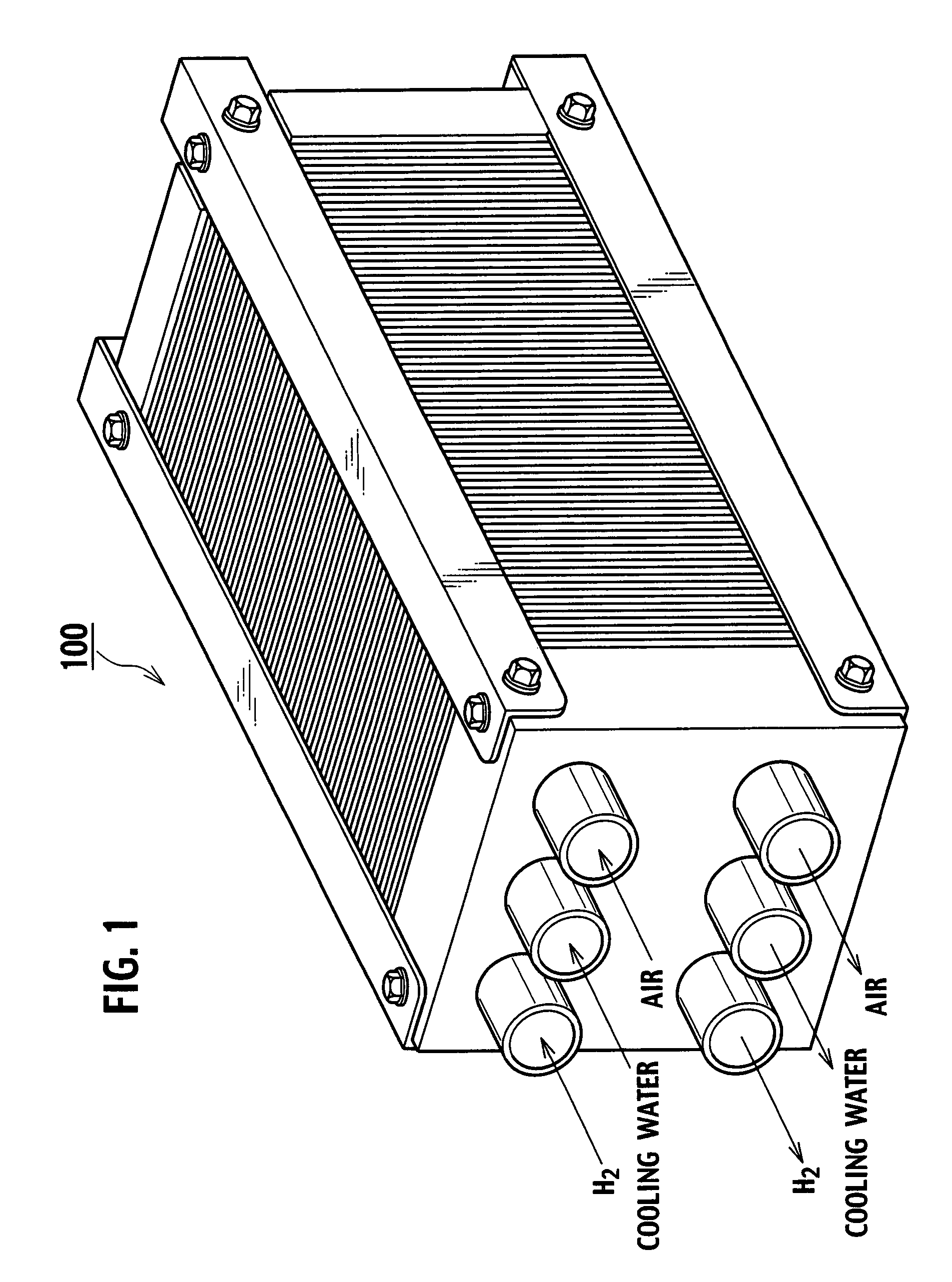
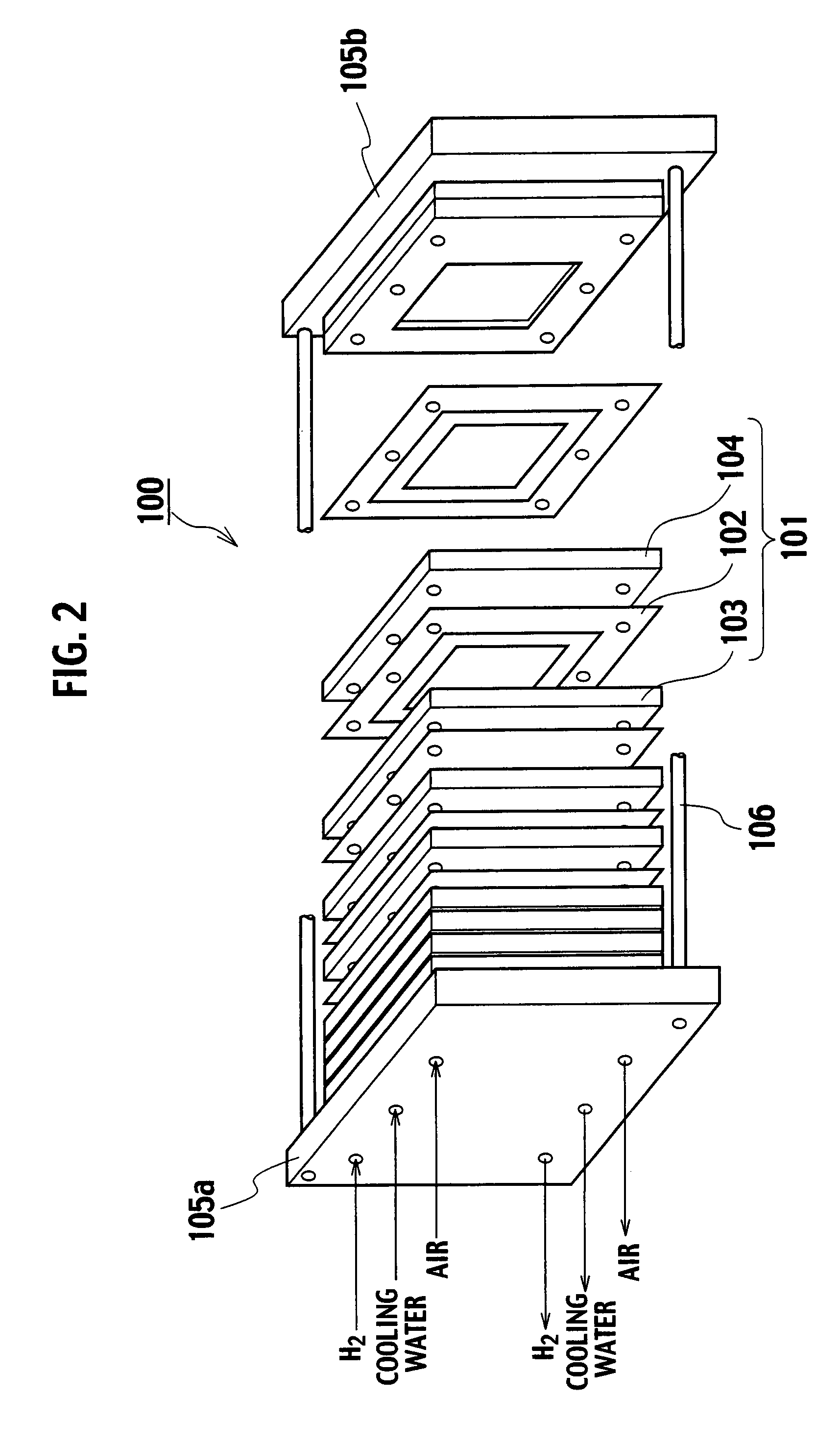
[0041]FIG. 1 is a perspective view of a fuel cell stack 100 with a polymer electrolyte fuel cell according to an embodiment of the present invention, and FIG. 2 schematically shows a partial section of the fuel cell stack 100. The fuel cell stack 100 is configured as a complex cell with a plurality of laminated single cells 101. The single cells 101 have an anode side separator 103 and a cathode side separator 104 residing on both sides of a membrane electrode assembly 102. The fuel cell stack 100 has end flanges 105a and 105b disposed at both ends of the plurality of laminated single cells 101, and is configured by fastening the outer peripheral parts with fastening bolts 106.
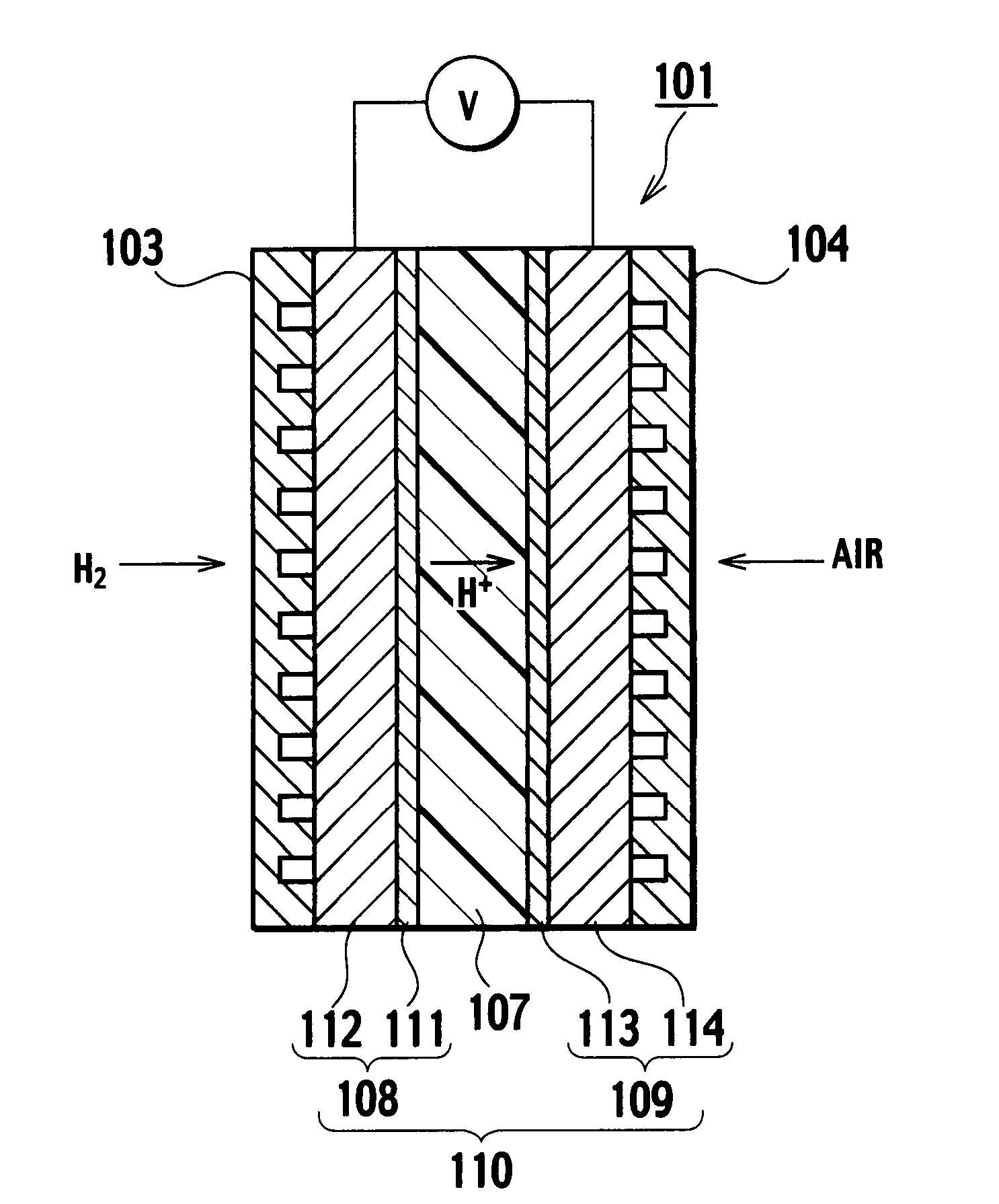
[0042] In addition, FIG. 3 shows a section of a single cell 101. This single cell 101 is configured in the form of a membrane electrode assembly 110 with an anode 108 and a cathode 109 disposed on both sides of a solid polymer electrolyte membrane 107, respectively, and an anode side separator 103 and a catho...
embodiment example 1
[Fabrication of Anode Catalytic Layer]
[0064] First, a carbon black (Ketjen Black International Ltd. make Ketjenblack™ EC, specific surface area BET=800 m2 / g, amorphous carbon) was prepared by 40 g, and 400 g of dinitro diammineplatinum solution (Pt concentration 1.0%) was added to that carbon black, which was stirred for one hour. Thereafter, 50 g of methanol was mixed thereto as a reducing agent, which was stirred for one hour, and then heated up to 80° C., stirred at 80° C. for six hours, and let to temperature-fall by one hour down to a room temperature. After a filtering of deposit, obtained solids were dried under a reduced pressure at 85° C. for 12 hours, and crushed in a mortar, obtaining carbon carriers supporting thereon 50 mass-% in Pt support concentration of Pt particles having an average particle size of 2.6 nm.
[0065] Next, to obtained carbon carriers having Pt particles supported thereon, 5 times their mass of purified water was added, and after five minutes of de-fo...
embodiment example 2
[0077] For an embodiment example 2, a single cell for evaluation was fabricated by using like method to the embodiment example 1, subject to a change of carbon carriers supporting catalyst particlers thereon in a cathode catalytic layer.
[0078] First, a high crystallinity carbon (Denki Kagaku Kogyo Ltd. make acetylene black CA-250) was prepared, with a specific surface area BET of 264 m2 / g, a mean lattice plane spacing d002 of 0.355 nm, and a crystallite size Lc of 3.6 nm.
[0079] To 4.0 g of this high crystallinity carbon, 400 g of dinitro diammineplatinum solution (Pt concentration 1.0%) was added, which was stirred for one hour. In addition, 50 g of formic acid was mixed thereto as a reducing agent, which was stirred for one hour, and thereafter, it was heated up to 40° C. by 30 minutes, and stirred at 40° C. for six hours. After a heating up to 60° C. by 30 minutes followed by an additional stirring at 60° C. for six hours, it was let to temperature-fall by one hour down to a roo...
PUM
 Abstract
Description
Claims
Application Information
 - R&D
- Intellectual Property
- Life Sciences
- Materials
- Tech Scout
- Unparalleled Data Quality
- Higher Quality Content
- 60% Fewer Hallucinations
Browse by: Latest US Patents, China's latest patents, Technical Efficacy Thesaurus, Application Domain, Technology Topic, Popular Technical Reports.
© 2025 PatSnap. All rights reserved.Legal|Privacy policy|Modern Slavery Act Transparency Statement|Sitemap|About US| Contact US: help@patsnap.com