Microwave heating method and apparatus for iron oxide reduction

a technology of iron oxide and heating method, which is applied in lighting and heating apparatus, manufacturing converters, furnaces, etc., can solve the problems of large amount of dust and waste energy, need for coke and intense high temperature combustion, and the price of scrap international has doubled, so as to avoid contamination of iron during production, the effect of reducing the cost and reducing the energy consumption

Inactive Publication Date: 2008-04-17
HWANG JIANN YANG +1
View PDF2 Cites 25 Cited by
  • Summary
  • Abstract
  • Description
  • Claims
  • Application Information

AI Technical Summary

Benefits of technology

[0013] It is a further object of the present invention to avoid contamination of iron during production with phosphorus, sulfur or silica using a minimum energy and at a lower cost.
[0014] It is still a further object of the invention to separate silica from the ore at a minimum consumption of energy.
[0015] The above recited objects and other objects which will be understood upon a reading of the following specification and claims a

Problems solved by technology

The fundamental problems associated with this production route are the needs for coke and intense high temperature combustion.
Coke making is one of the most polluting of industrial processes and high temperature combustion generates a great amount of dust and wastes energy in the exhaust gases.
Minimills traditionally enjoyed an abundant supply of steel scrap, however, the recent strong demand for scrap internationally has doubled the price.
DRI prices have also significantly increased due to high cost of reformed natural gas, causing many DRI plant closings.
Another problem with iron and steel making has been the retention of sulfur and phosphorus in the iron which may reduce the quality of the iron or steel produced.
This problem results from the much higher temperatures typically reached in conventional reducing of iron oxide by combustion of natural gas or coal.
This problem is exacerbated if coal is used to reduce the ore or other feedstock since coal sometimes contains sulfur, and this would further increase the level of sulfur in the iron.
A further problem resulting from the high temperatures required in conventional reduction processes is that expensive refractory material must

Method used


Image

  • Microwave heating method and apparatus for iron oxide reduction
  • Microwave heating method and apparatus for iron oxide reduction
  • Microwave heating method and apparatus for iron oxide reduction

Examples


Embodiment Construction

[0039] In the following detailed description, certain specific terminology will be employed for the sake of clarity and a particular embodiment described in accordance with the requirements of 35 USC 112, but it is to be understood that the same is not intended to be limiting and should not be so construed inasmuch as the invention is capable of taking many forms and variations within the scope of the appended claims.

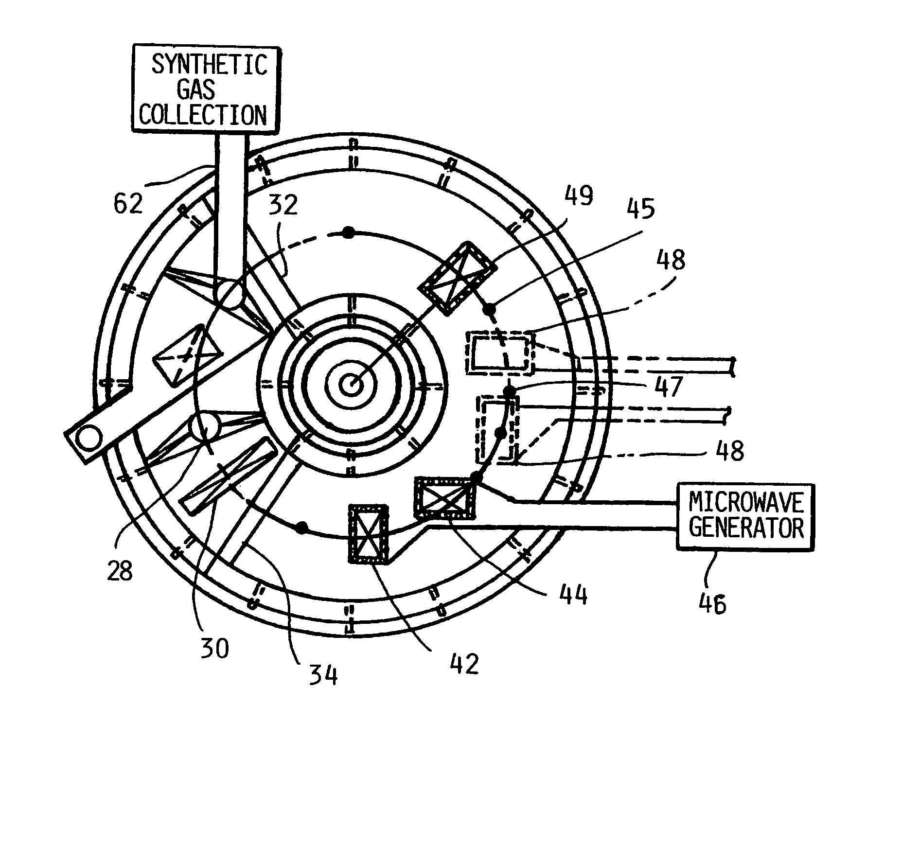
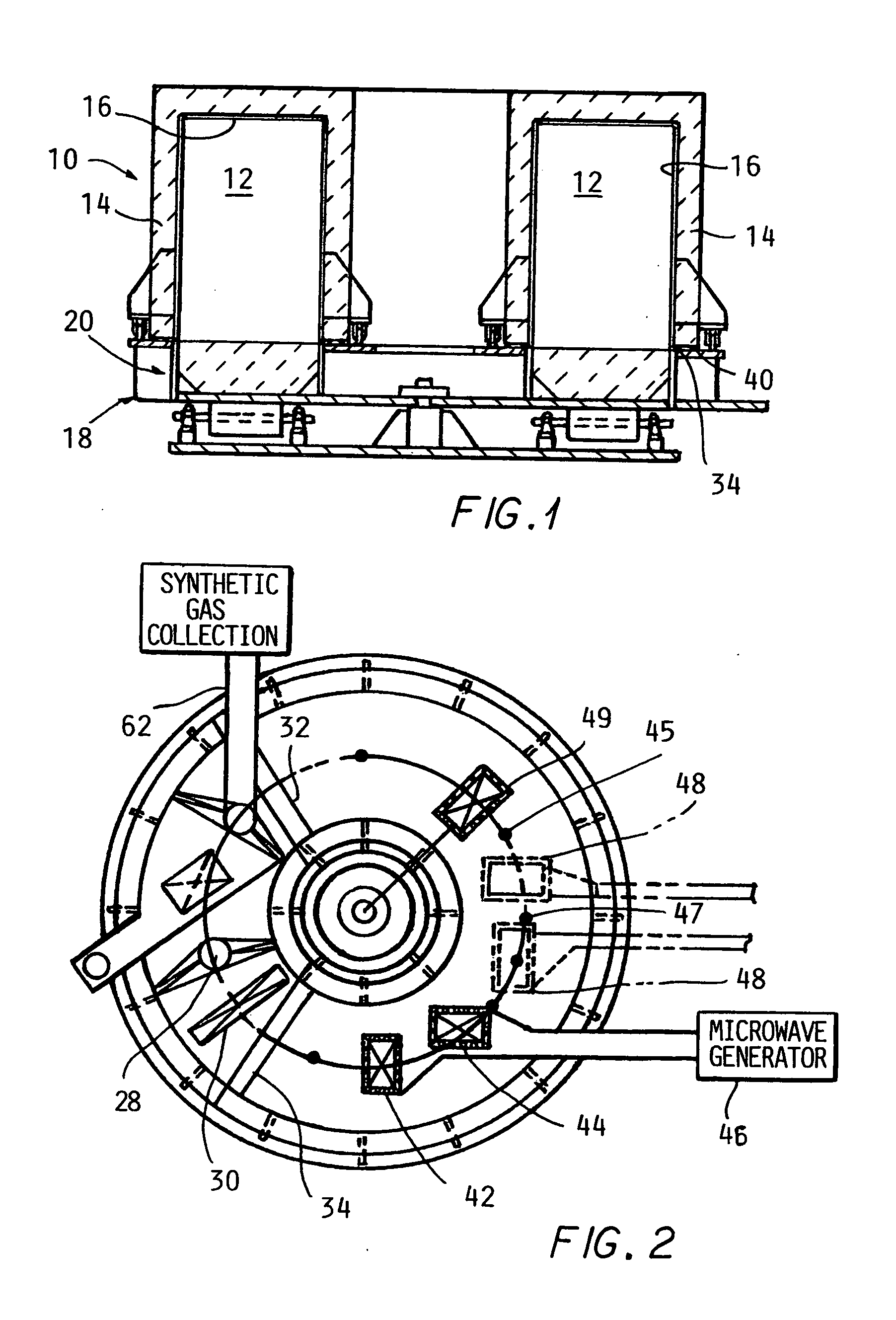
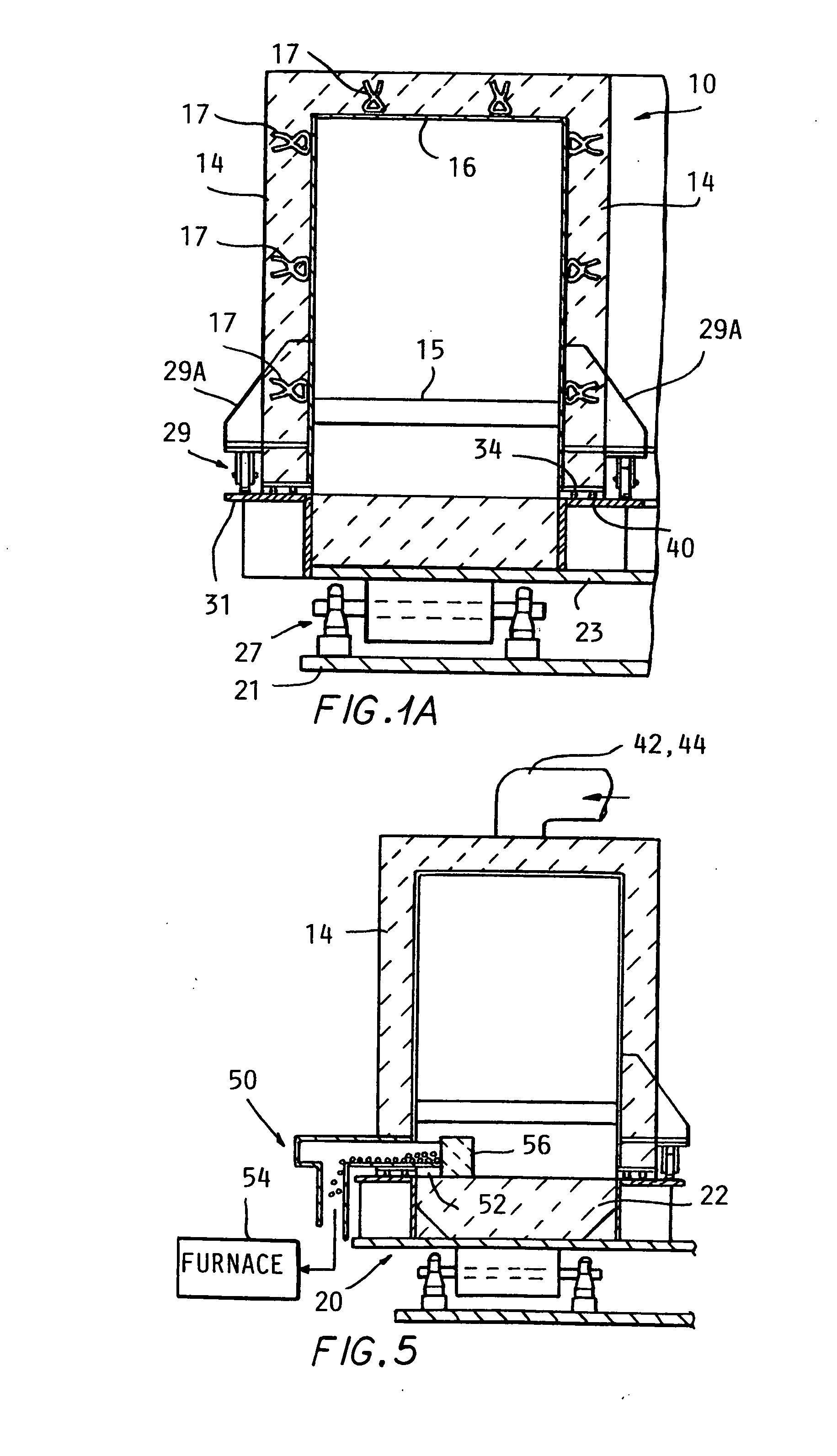
[0040] Referring to the drawings and particularly FIGS. 1-5, a rotary hearth furnace 10 according to the present invention is depicted. This comprises a stationary annular upper chamber 12 having outer walls 14 of a refractory insulating material and an inner skin 16 of stainless steel attached to embedded anchors 17 in the refractory walls 14. A rotating base assembly 18 supports a ring shaped hearth 20 which is rotated beneath the stationary annular chamber 12 by a motor—right angle drive 24 and chain 26. A series of main rollers 27 are mounted on a base plate 21 and...


PUM

PropertyMeasurementUnit
Temperatureaaaaaaaaaa
Contentaaaaaaaaaa
Refractoryaaaaaaaaaa

Abstract

A method and apparatus for reducing iron oxides using microwave heating in a furnace chamber which is sealed against the entrance of air reduces the energy required and produces a low temperature reduction and allows the recovery of combustible synthetic gas as a byproduct of the process. Avoidance of the reduction of sulfur, phorphorus and silica is also insured, as is the need to reduce the silica content of the feed material prior to reducing the ore. A continuous rotary hearth furnace, a rotary kiln, a linear conveyor and vertical shaft furnace chamber configurations are described. A secondary heating zone can also be included to process the reduced iron into iron nuggets or liquid metallic iron.

Description

CROSS REFERENCE TO RELATED APPLICATIONS [0001] This application claims the benefit of U.S. provisional patent application Ser. No. 60 / 849,098 filed on Oct. 3, 2006 and Ser. No. 60 / 865,672 filed on Nov. 14, 2006, and is a continuation in part of U.S. patent application Ser. No. 11 / 220,358 filed on Sep. 6, 2005 which claimed the benefit of U.S. provisional patent application Ser. No. 60 / 607,381 filed on Sep. 3, 2004 and U.S. provisional patent application Ser. No. 60 / 607,140 filed on Sep. 3, 2004.BACKGROUND OF THE INVENTION [0002] Currently steel is produced by two types of operations: integrated mills and minimills. In the integrated mill, sintered iron ore pellets, coke and lime are charged into a blast furnace (BF). Air is blown in at high speed to combust the coke to generate carbon monoxide and heat. Sintered iron ore pellets are reduced to hot metal by the carbon monoxide and melted to form liquid iron. The liquid iron is then sent to a basic oxygen furnace (BOF) where pure oxyg...

Claims


Application Information

Patent Timeline
IPC IPC(8): C21C5/52C21B11/06C21C5/38
CPCC21B13/0046C21B13/08C21B13/105C21B2100/02F27B9/36F27B1/10F27B7/34F27B9/16C21C5/567Y02P10/122Y02P10/134
Inventor HWANG, JIANN-YANGHUANG, XIAODI
Owner HWANG JIANN YANG
Why Eureka
Try Eureka