
Instrument for Delivery of Optical Energy to the Dental Root Canal System for Hidden Bacterial and Live Biofilm Thermolysis

a technology of optical energy and root canal system, which is applied in the direction of teeth capping, teeth nerve/root treatment implement, etc., can solve the problems of slow ablation rate of mid-infrared laser, limited acceptance of laser use for endodontic therapy, and inability to deliver optical energy in a single direction, etc., to achieve long treatment time, low infrared energy, and low energy consumption

Inactive Publication Date: 2008-06-12
NOMIR MEDICAL TECH
View PDF1 Cites 28 Cited by
  • Summary
  • Abstract
  • Description
  • Claims
  • Application Information

AI Technical Summary

Benefits of technology

"The present patent is about a system and method for using a flexible optical probe and laser to remove bacteria and biofilm from the root canal of a human tooth. The optical probe disperses low infrared energy throughout the root canal, targeting bacteria and live biofilm without creating a \"hot tip\". The laser induces thermotherapy within the root-canal space, resulting in a 360-degree scattering of the optical energy. This technique allows for longer treatment times without charring or melting in the root canal space."

Problems solved by technology

Even so, the acceptance of laser use for endodontic therapy has remained limited.
This is due to the inherent problems of unidirectional optical energy delivery within the confines of the root canal space.
However, when compared to classical mechanical debridement, ablation rates with the mid-infrared lasers are slow, and the beam can only exit the delivery tip in one direction (either vertically or horizontally).
In the earlier generation of laser delivery devices, it was very difficult if not impossible to deliver optical energy to the apical third of the root canal system.
The fiber delivery of the previous art, however, has presented a series of problems that were not overcome.
If the temporal pulses are too long (or the exposure in CW is too long), the thermal relaxation effect in the tissues is overcome and irreversible damage to non-target areas may occur.
This debris will absorb the intense infrared laser energy propagating through the fiber, which will cause the tip to heat and immediately carbonize the tissue detritus.
The carbonization of the fiber tip leads to an increase in temperature, and this can result in significant damage to the optical quality of the fiber (the temperature spikes to greater than 9000 C).
They also found that, once the carbonization of the tip occurs, the tip no longer functions as an adequate light guide.
The laser will no longer adequately photocoagulate with primary photons, but rather it will incise and cauterize the tissue because of the intense heat at the tip.
Furthermore, longer lasing times and higher power drastically reduces the forward power transmission of the laser radiation, as the fiber tip sustains more and more heat induced damage.
Further loss was observed as the irradiation period of time continued and tissue debris accumulated.
With the conventional fiber tips, histology and thermal imaging demonstrated deleterious effects deep into the tissue.
As a result, optical transmission qualities are damaged.
Also of significance, as the quality of the fiber transmission diminishes as a result of damage to the tip, the energy, focus, and homogeneity of the energy being transmitted from the tip is affected.
The primary energy that is still available for forward power transmission out of the tip is far less efficient for tissue penetration and photocoagulation.
That is a difficult standard to uphold and keep.

Method used


Image

  • Instrument for Delivery of Optical Energy to the Dental Root Canal System for Hidden Bacterial and Live Biofilm Thermolysis
  • Instrument for Delivery of Optical Energy to the Dental Root Canal System for Hidden Bacterial and Live Biofilm Thermolysis
  • Instrument for Delivery of Optical Energy to the Dental Root Canal System for Hidden Bacterial and Live Biofilm Thermolysis

Examples


Embodiment Construction

[0010]Current Model for Infected Root Canal Space and Apical Periodontitis

[0011]When a vital dental nerve (pulp) becomes infected with pathogenic microorganisms, it undergoes a process of irreversible pulpitis. This occurs when the local inflammatory products and tissue damage, from the bacterial infiltration, cause the dental pulp to succumb and die. This cascade then turns into a frank micro-abscess within the pulp chamber and the accompanying dental root canal three-dimensional structure. As the infection progresses, the entire soft-tissue of the dental pulp undergoes a process of liquefaction necrosis. Within the hard dental canal structure, there results a complete lack of collateral circulation and, subsequently, insufficient drainage available for the necrotic inflammatory fluids within the root canal space. The inflammatory bacteria laden fluids then escape the root canal system at the root apex, and begin to cause a massive inflammatory response at the periapex in the richl...


PUM

PropertyMeasurementUnit
infrared wavelength rangeaaaaaaaaaa
lengthaaaaaaaaaa
diameteraaaaaaaaaa

Abstract

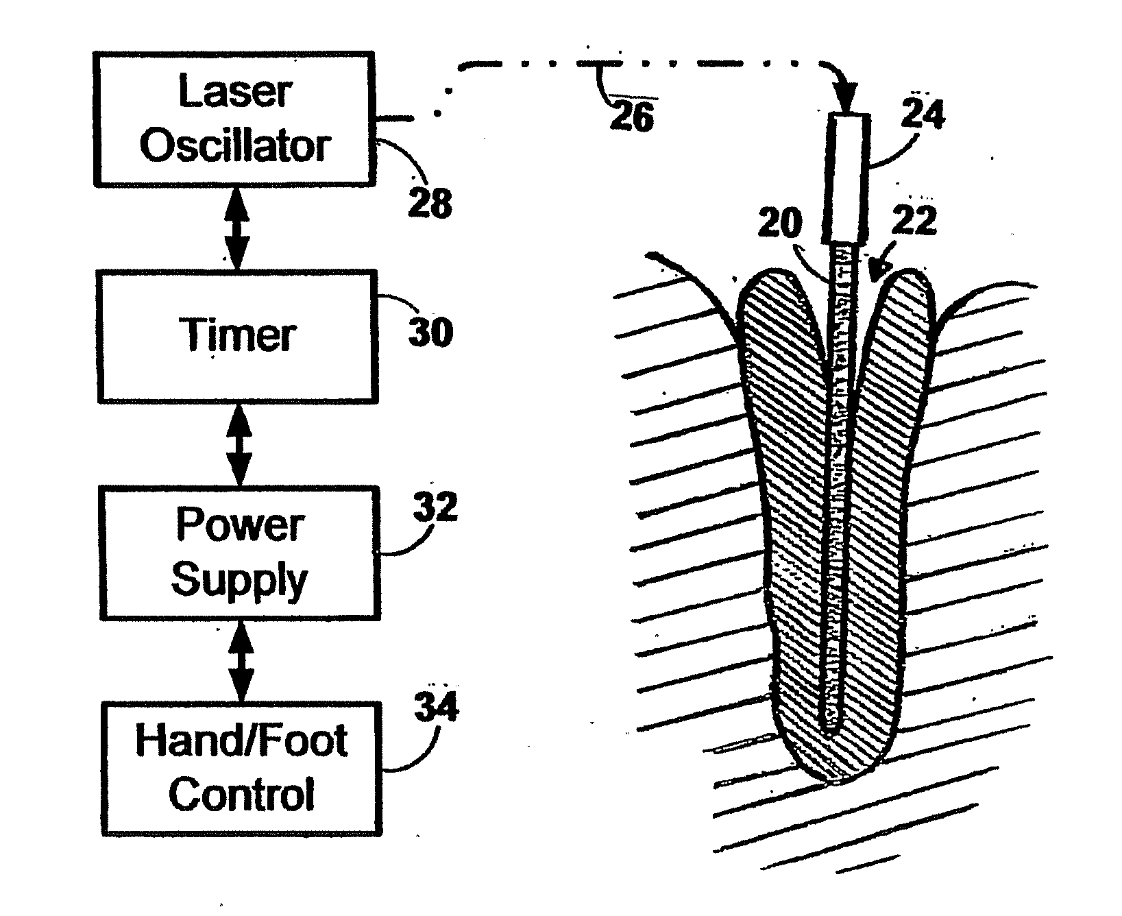
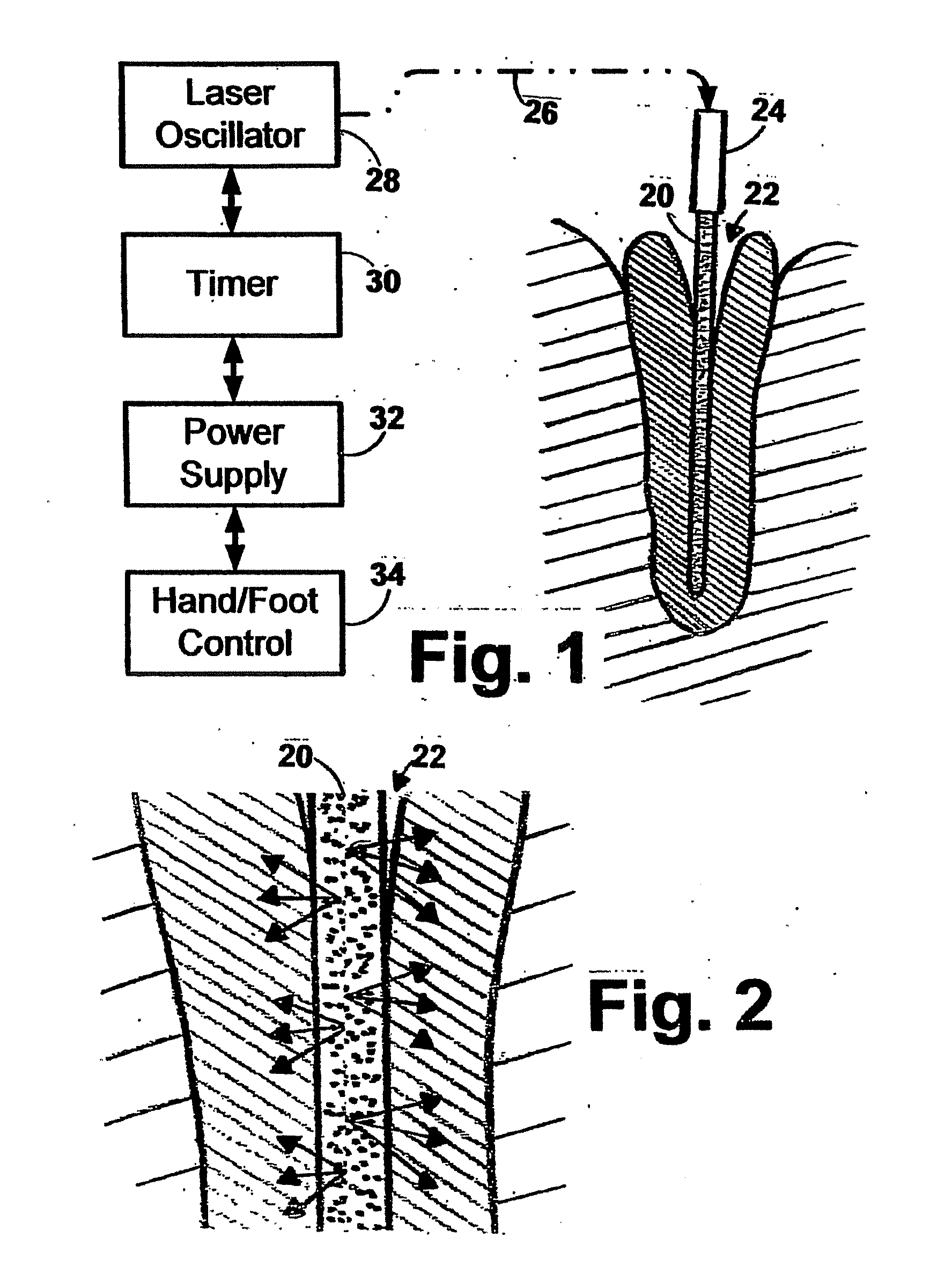
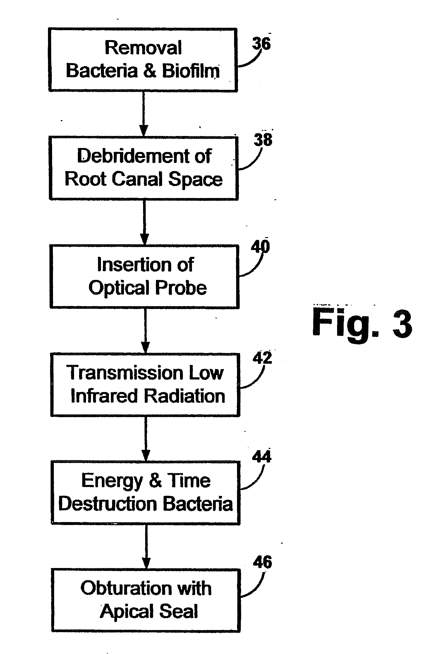
Systems, processes, techniques, and apparatus are described for thermolytic eradication of bacteria and biofilm in the root canal of a human tooth involve an elongated and flexible optical probe and a laser oscillator that provides the probe with near infrared energy. The optical probe can be sufficiently long for insertion into substantially the entire length of the root canal of the tooth. The optical probe causes lateral dispersion of the radiation from the probe throughout the root canal. The radiation is provided at an energy density and for a period of time that are necessary to selectively target bacteria and live biofilm in the dentinal tubules of an entire root canal system, at once, thereby (1) inhibiting creation of a blackbody “hot tip”, and (2) inducing laser interstitial thermotherapy (LITT) within the root-canal space. Near infrared wavelengths from about 700 nm through about 1100 nm can be used.

Description

CROSS REFERENCE TO RELATED APPLICATIONS[0001]This application is a continuation application of U.S. patent application Ser. No. 10 / 821,442, filed Apr. 9, 2004, which application claims priority to U.S. Provisional Application No. 60 / 468,944, filed May 8, 2003, both of which applications are incorporated herein by reference in their entireties.BACKGROUND[0002]Various laser and fiber delivery systems have been proposed for the express purpose of disinfecting or sterilizing tissues in a three-dimensional root canal system. Generally, such systems are limited to unidirectional energy delivery or to the generation of a blackbody incandescent “hot tip” at the distal end of an optical delivery fiber path. Such delivery of energy occurs when an unclad “naked’ fiber tip comes in contact with tissue and fluid in root canal space. In this instance, debris will accumulate on the tip immediately, and this debris will absorb the intense infrared laser energy propagating through the associated opt...

Claims


Application Information

Patent Timeline
Patent Type & Authority Applications(United States)
IPC IPC(8): A61C5/02A01H1/00A01H5/00A61C1/00A61C3/00A61C5/04C12N15/82
CPCA61C1/0046A61C5/02A61C5/04A61N2005/067A61N5/0624A61N2005/0651A61N2005/0659A61N5/0613A61C5/40A61C5/50A61N5/067
Inventor BORNSTEIN, ERIC
Owner NOMIR MEDICAL TECH
Learn More