
Optical Thin Films with Nano-Corrugated Surface Topologies by a Simple Coating Method

a coating method and optical thin film technology, applied in the direction of discharge tube luminescnet screen, discharge tube/lamp details, organic semiconductor devices, etc., can solve the problems of multiple steps in processing, overheating of the device, and affecting the lifetime and use of the device, so as to enhance the light extraction efficiency of the light emitting device and the effect of enhancing the light extraction efficiency

Inactive Publication Date: 2008-07-03
OPTIMAX TECHNOLOGY CORPORATION
View PDF0 Cites 22 Cited by
  • Summary
  • Abstract
  • Description
  • Claims
  • Application Information

AI Technical Summary

Benefits of technology

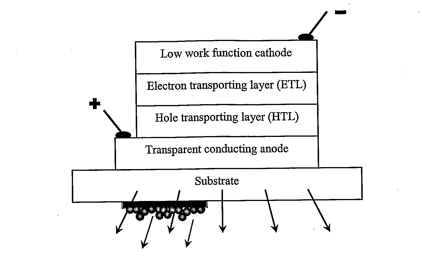
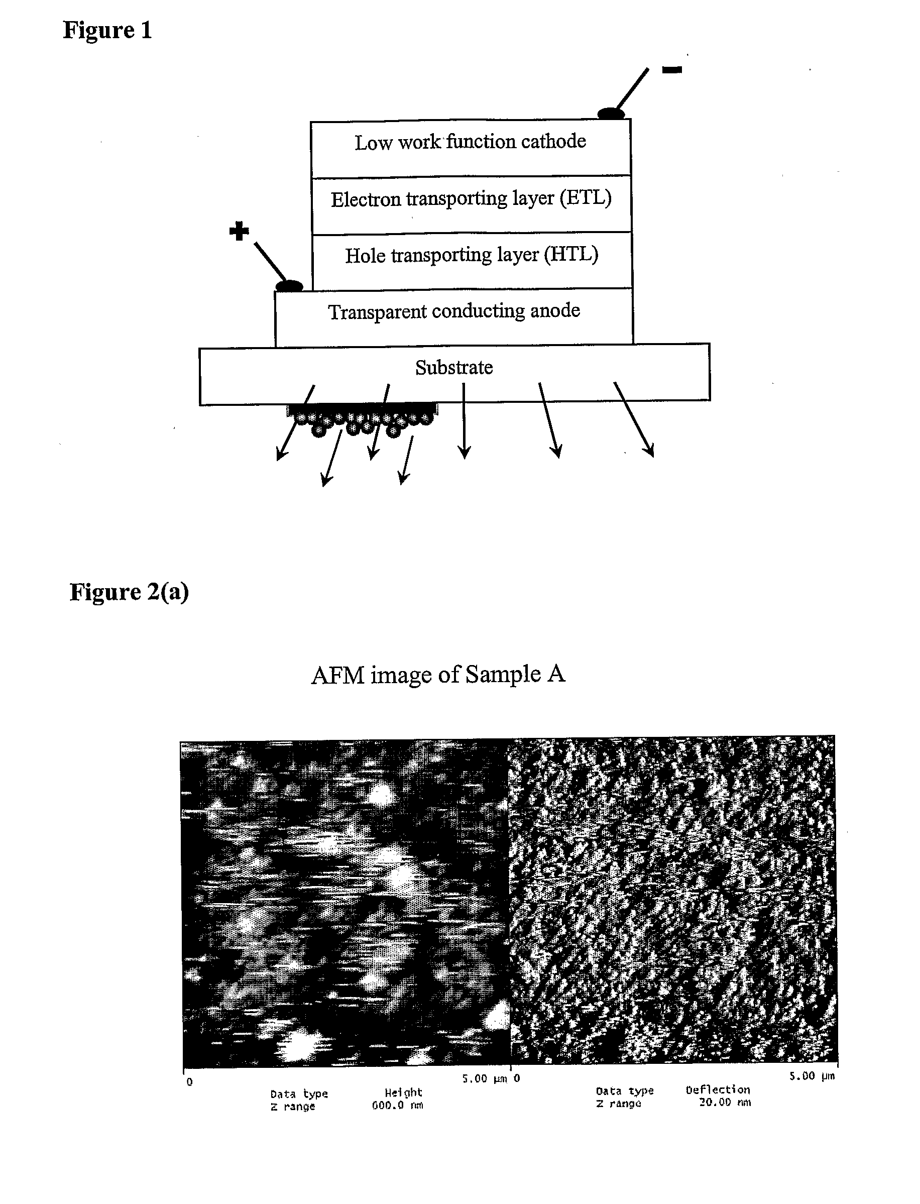
[0012]The present invention, in various embodiments thereof, provides an inexpensive method to produce an inorganic-organic thin film having a well-controlled surface morphology and a refractive index matching to that of the encapsulated material, which may be, for example, either plastic or glass. The coating can be applied by dip or spin coating or other wet coating methods on the surface of a substrate prior or after manufacturing the light emitting device.
[0013]An inorganic-organic self assembled functional coating, which offers an easy and effective way to fabricate visible light wavelength scale microstructures on both glass as well as plastic substrates is described below.
[0014]In addition, because the creation of the surface morphology is accomplished by using nanoparticles in an ordinary coating process, it can be easily integrated with other functional coatings, such as quantum dots, fluorescent core-shell nanoparticles, and metal nanomaterials, to further enhance the light extraction efficiency of the solid state lighting devices. For example, as demonstrated by examples of embodiments of this invention, as presented hereinafter, the functional coating can be used as the effective binding matrix for highly efficient phosphor materials, such as quantum dots or fluorescent core-shell nanoparticles, to make high bright white light emitting devices. In addition, the surface corrugation can be easily created with a functional coating of good mechanical properties to provide protection against abrasions and scratches. Either a sol-based binder or a polymer-based binder may be used to enhance the adhesion between silica particles as well as to match the refractive index of the nanoparticles. As an example, inorganic-organic hybrid coating compositions based on a UV-curable or heat-curable binder and inorganic particles with special surface modification have been developed according to embodiments of this invention.

Problems solved by technology

Because of efficiency requirements of portable devices and detrimental effects of excessive heat, light outcoupling has become one of the central issues in improving light emitting devices.
The trapped amount of power is eventually converted to heat, which leads to overheating of the device and is detrimental to the lifetime and usage of the device.
However, all these methods require not only sophisticated equipment, but also multiple steps in processing and excessive energy input to generate the desired periodic photonic type structures.

Method used


Image

  • Optical Thin Films with Nano-Corrugated Surface Topologies by a Simple Coating Method
  • Optical Thin Films with Nano-Corrugated Surface Topologies by a Simple Coating Method
  • Optical Thin Films with Nano-Corrugated Surface Topologies by a Simple Coating Method

Examples


example 1 to example 4

Fluorinated Silica Particle Preparation

example 1

[0056]In a reaction vial, 100 ml isopropanol (IPA), 14 ml tetraethoxysilane (TEOS) and 6 ml tridecafluoro-1,1,2,2-tetrahydrooctyl)triethoxysilane (F-TEOS) were added and mixed with a magnetic stirrer at a high speed for two minutes. While stirring, between 0.5 and 20 ml deionized water and between 0.5 and 10 ml concentrated ammonia solution (NH3 28-30 wt % in water) were added into the mixture. The mixture was stirred over a period of 30 to 240 minutes. The initially clear mixture became a translucent suspension. The suspension was aged for two days and then the particle size was determined by laser light scattering. The medium for particle sizing was ethanol. The particle suspensions were treated by ultrasound for 5 to 10 minutes before particle sizing. The fluoro-content in the particles was calculated based on the molar ratios of the reactants.

[0057]The average particle diameter prepared from above procedure is about 120 nm. The molar ratio of F-containing silica to pure silica i...

example 2

[0058]In a reaction vial, 100 ml isopropanol, 14 ml (TEOS) and 2.6 ml (F-TEOS) were added and mixed with a magnetic stirrer at a high speed for two minutes. During the stirring, between 0.5 and 20 ml of deionized water and between 0.5 and 20 ml concentrated ammonium hydroxide solution (NH3 28-30 wt %) were added to the mixture. The mixture was stirred over a period of 30 to 240 minutes. The initially clear mixture develops into an opaque white suspension. The suspension was subsequently aged for two days and then the particle size was determined by laser light scattering. The particle size is around 400 nm. The molar ratio of F-containing silica to pure silica in the particles is 10:90.


PUM

PropertyMeasurementUnit
particle sizeaaaaaaaaaa
temperatureaaaaaaaaaa
thicknessaaaaaaaaaa

Abstract

Embodiments of the invention relate to functionalized nanoparticle coating compositions. These coating can improve the light extraction efficiency of light emitting devices, including LEDs and OLEDs. In some embodiments, the coating can improve other properties such as anti-staining, abrasion and / or scratch resistance.

Description

CROSS-REFERENCE TO RELATED APPLICATION[0001]This application claims benefit of U.S. Provisional Application No. 60 / 656,097 filed Feb. 25, 2005. This application, in its entirety, is incorporated herein by reference.BACKGROUND OF THE INVENTION[0002]An embodiment of this invention relates to inorganic-organic self assembled functional coatings that can easily achieve a well controlled surface topography at the visible light wavelength scale. Embodiments of the invention may be used to improve light extraction efficiency in light emitting devices (LED) and organic light emitting devices (OLED).[0003]At present, LEDs are the most efficient sources of colored light in almost the entire visible spectral range. Solid-state lighting may use visible and / or ultraviolet LEDs that are expected to reach lifetimes exceeding 100,000 hours. Using organic materials for light emitting devices (LED) has also gained tremendous interest due to their versatility in processing and the relative ease of com...

Claims


Application Information

Patent Timeline
Patent Type & Authority Applications(United States)
IPC IPC(8): H01J1/62B05D5/12H01L33/44
CPCB82Y20/00B82Y30/00H01L33/44H01L2251/5369H01L51/5262H01L51/5265H01L51/5036H10K50/125H10K50/852H10K50/85H10K2102/331
Inventor WU, XIAODONGYANG, ARTHUR JIN-MINGZHANG, RUIYUN
Owner OPTIMAX TECHNOLOGY CORPORATION
Learn More