Biomolecule Immobilization on Biosensors

a biosensor and biomolecule technology, applied in the field of surface modification of a substrate, can solve the problems of requiring covalent interaction between substrate and probe, generally negatively charged glass, and strong attachmen

Inactive Publication Date: 2008-07-03
THE BOARD OF TRUSTEES OF THE LELAND STANFORD JUNIOR UNIV
View PDF10 Cites 96 Cited by
  • Summary
  • Abstract
  • Description
  • Claims
  • Application Information

AI Technical Summary

Benefits of technology

[0018]In one aspect, the present invention provides a method of linking biomolecules to solid supports, or substrates (e.g., glass or SiO2), using layers of polymers for covalent attachment of the biomolecules. In a first step, molecules or polymers bearing amine groups are introduced onto the solid substrates; amine reactive polymers are then coated onto the amine modified substrates. The immobilized amine reactive polymer film can then be used to couple biomolecules having amine groups, such as amino-oligos or proteins with amine side chains, such that the reactive groups on the polymer serve as a linking reagent between the biomolecules and the solid substrate. A preferred method is to attach an amino-modified oligonucleotide directly to an activated anhydride polymer. The preferred process uses an aqueous solution of partially hydrolyzed polymer obtained by heating a low concentration (e.g., 2%, or less than 10%) of the anhydride suspension in water. Hydrolysis is necessary to make an aqueous solution since non-hydrolyzed polymer is not soluble in water. Once the partially hydrolyzed polymer is coupled, it can be converted to a non-hydrolyzed polymer again by heating. Heating may be done at a relatively low temperature, e.g., about 90-110° C., or as high as 200° C., but preferably e.g., at about 100° C. Thus, the preferred process is very clean and simple and does not require toxic organic solvents.

Problems solved by technology

For example, a glass is generally negatively charged when in a neutral or basic solution.
In general, however, simple adsorption does not provide strong enough attachment and thus covalent interaction between substrate and probes is required.
When the probes are bound on a flat substrate, the steric crowding between the probes is thought to be responsible for low capture efficiency as observed in some arrays.
As a silanization process, such a method involves organic solvents and may have variable results due to reproducibility problems in the process.
Surface chemistries developed for conventional microarrays, however, are not easily adopted in these BioMEMS systems.
First, the microfabrication process often involves elevated temperatures and harsh chemical and physical treatments that can denature or damage biomolecules; second, DNA immobilization chemistries always start with a strong acid cleaning such as Piranha or a strong base cleaning such as RCA to activate the substrates, a harsh condition that the components (e.g., sensors) of a MEMS device can rarely survive.
It is thus very challenging to integrate biomolecules into common microfabrication processes (REF 4).

Method used


Image

  • Biomolecule Immobilization on Biosensors
  • Biomolecule Immobilization on Biosensors
  • Biomolecule Immobilization on Biosensors

Examples


example 1

Chip Fabrication

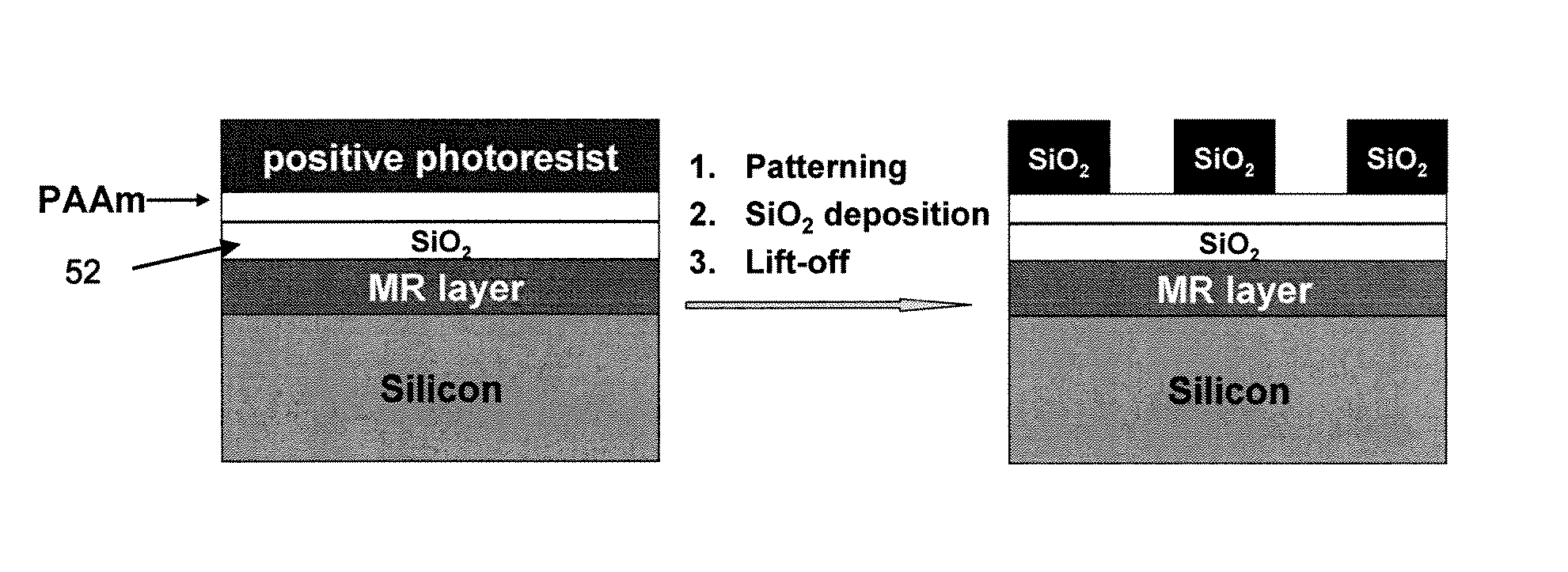
[0078]As shown in FIG. 5, a silicon substrate containing an MR (magnetoresistance) layer was prepared as a spin valve. Spin valve magnetic sensors were fabricated from 4-inch silicon wafers containing layers Si / Ta 3 nm / seed layer 4 nm / PtMn 15 nm / Co90Fe10 2 nm / Ru 0.85 nm / Co90Fe10 2 nm / Cu 2.3 nm / Co90Fe10 2 nm / Cu 1 nm / Ta 4 nm with a magnetoresistance (MR) of 10.3% and a sheet resistance of 18.41Ω. Next, a silicon oxide layer 52 was added by sputter coating. This serves as a passivation layer and may be about 10-20 nm thick. Other passivation layers (e.g., silicon nitride or a combination of silicon oxide and silicon nitride) may be used.

[0079]Next, the prepared substrate having a thin SiO2 passivation layer was coated with polyallylamine (PAAm) and heated at 170° C. for 2 min. A whole wafer was coated with PAAm by immersing the wafer into a 2 wt % PAAm in water solution for 30 seconds, rinsing with water, and blowing dry. The thickness of the polymer film was characteri...

example 2

Hybridization Assays

[0085]Target hybridization was performed at room temperature under 100% humidity overnight in MES buffer (0.1 MES, 0.9M NaCl, pH 6.5). The chip was then rinsed with PBS buffer containing 0.01% Tween 20 three times, each for 1 min and finally blown dry with argon.

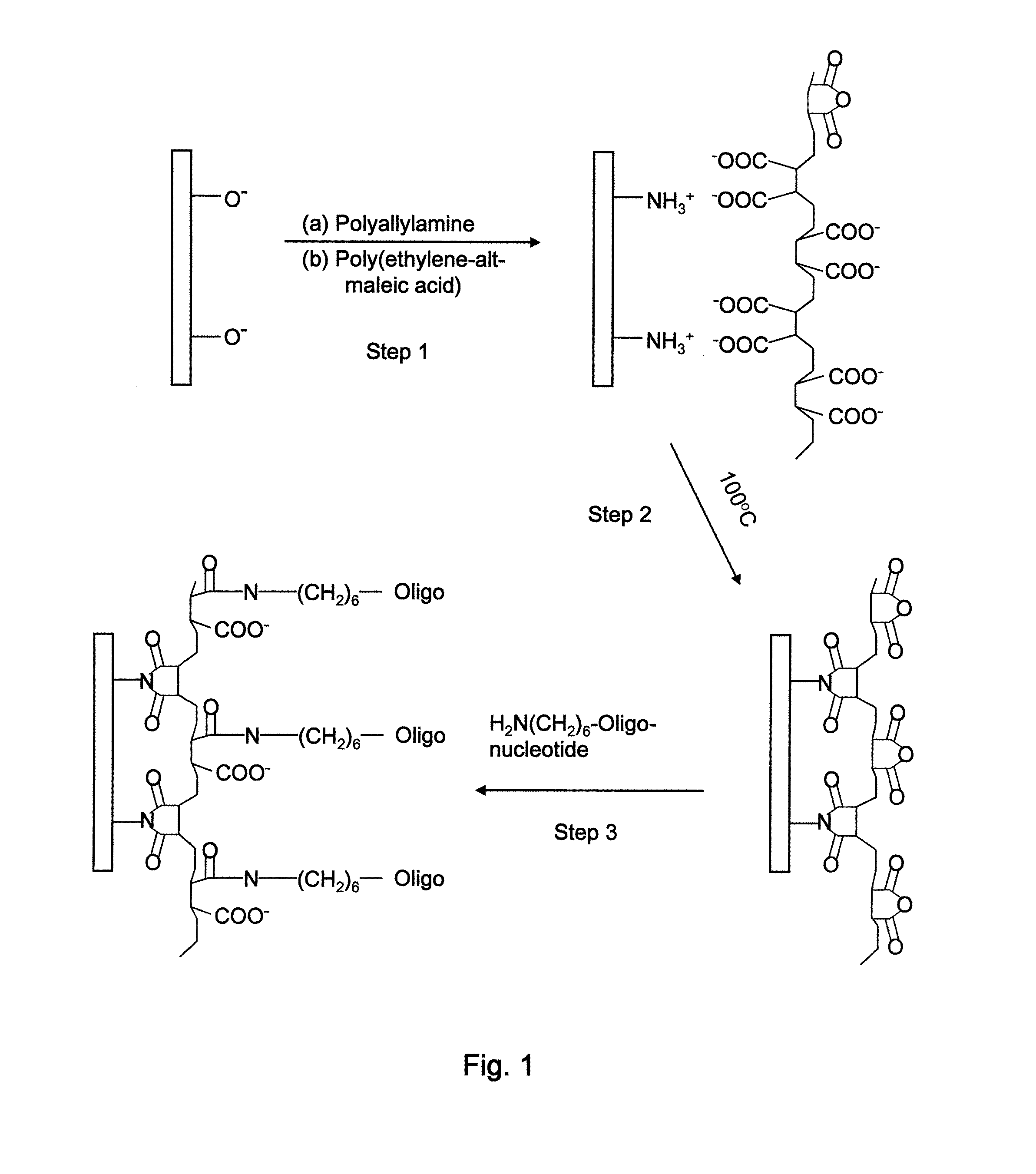
[0086]The general assay format for the present work is shown in FIG. 3(G). The probe is the oligo as shown in FIG. 1, attached to a substrate. The target DNA, if complementary, will bind to the probe, and bears a biotin label. This label is in turn tagged with a streptavidin-coated magnetic nanoparticle.

[0087]Hybridization assays were conducted on a duplex microarray (i.e., having two complete sets of probes) to demonstrate the performance of the present surface chemistry. Solutions of positive and control oligonucleotide probes bearing amino groups on the 5′-end were manually spotted to different sensors on the same chip following surface activation. The sensors were then blocked with ethanolamine and hy...

example 3

Magnetic Sensor Measurements

[0089]The success of the surface chemistry was further confirmed by real-time measurement of magnetic sensors. The two positive sensors were coated with 5′-5AmMC6 / TTT TTT TTT TCT ACC AAT CCA CAA ATA CCC ATC TAC CAT A-3′ (SEQ ID NO:4) probes, while the two control probes were coated with 5′-5AmMC6 / TTT TTT TTT-3′ (SEQ ID NO:2) probes. The positive probe sequence listed here can be seen to have a poly T spacer which will be adjacent the substrate and provides space for hybridization without interference by the substrate. The notation 5AmMC6 refers to a six-carbon linker and an amino group attached to the end. The DNA target used for hybridization was biotin5 / 5Biotin / TAT GGT AGA TCC GTA TTT GTG TTT GTG GAT TGG-3 (SEQ ID NO: 3) at a concentration of 10 nM. 5 / 5Biotin means that the biotin is attached to the 5′ end of the oligo.

[0090]FIG. 4(A) shows a real time response of sensors by applying magnetic nanoparticle solution to a chip having hybridized with target...


PUM

PropertyMeasurementUnit
temperatureaaaaaaaaaa

Abstract

A highly specific and versatile surface chemistry for immobilization of amine-terminated probes is disclosed. A bi-layered polymer thin film serves as the platform for coupling the probes, which are preferably oligonucleotides. The process involves sequentially coating a substrate with polyamine and polyacid anhydride. Hydrolyzed polyacid anhydride groups may be converted to non-hydrolyzed groups at about 100° C. prior to probe attachment. The process of coating the substrate requires no harsh chemical pretreatment of substrates such as RCA or Piranha cleaning. In addition, simple thermal activation of the anhydride groups has a low requirement for storage, leading to a long shelf life of modified surfaces. The disclosed surface chemistry is especially compatible with microfabrication processes, and its effective application to magnetic biosensors is demonstrated.

Description

CROSS-REFERENCE TO RELATED APPLICATIONS[0001]This Application claims priority to U.S. Provisional Patent Application No. 60 / 872,808, filed Dec. 5, 2006, which is incorporated herein by reference.STATEMENT OF GOVERNMENTAL SUPPORT[0002]This invention was made with U.S. Government support under NIH Grant POI-HG00025, NIH IU54CA119367-01, and DARPA grant N000140210807. The U.S. Government has certain rights in this invention.REFERENCE TO SEQUENCE LISTING, COMPUTER PROGRAM, OR COMPACT DISK[0003]Applicants assert that the paper copy of the Sequence Listing is identical to the Sequence Listing in computer readable form found on the accompanying computer disk. Applicants incorporate the contents of the sequence listing by reference in its entirety.BACKGROUND OF THE INVENTION[0004]1. Field of the Invention[0005]The present invention relates to the field of surface modification of a substrate so that a biomolecule may be attached to it.[0006]2. Related ArtBACKGROUND[0007]The attachment of bio...

Claims


Application Information

Patent Timeline
Patent Type & Authority Applications(United States)
IPC IPC(8): C40B40/00C40B50/18
CPCC40B40/08C40B40/10G01N33/54353C40B60/12C40B50/18
Inventor YU, HENGPOURMAND, NADERWANG, SHAN X.
Owner THE BOARD OF TRUSTEES OF THE LELAND STANFORD JUNIOR UNIV
Why Eureka
Try Eureka