Polymer, polymer electrolyte membrane for polymer electrolyte fuel cell, and membrane/electrode assembly

a technology of electrolyte fuel cells and polymer electrolyte, which is applied in the direction of fuel cells, electrochemical generators, non-aqueous electrolytes, etc., can solve the problems of insufficient mechanical strength of the resulting polymer electrolyte membrane, excessive swollen with water, and low molecular weight of the polymer, and achieves low electrical resistance , the effect of softening temperatur

Active Publication Date: 2008-08-14
ASAHI GLASS CO LTD
View PDF5 Cites 17 Cited by
  • Summary
  • Abstract
  • Description
  • Claims
  • Application Information

AI Technical Summary

Benefits of technology

[0010]The present invention provides a polymer having a low electrical resistance, having a softening temperature higher than that of a conventional polymer for an electrolyte membrane and being highly flexible; a polymer electrolyte membrane for polymer electrolyte fuel cells having a low electrical resistance, having heat resistance higher than that of a conventional electrolyte membrane and being less likely to be broken even when it undergoes repeats of swelling in a wet state and shrinkage in a dry state; and a membrane / electrode assembly having high power generation performance, capable of power generation at a temperature higher than conventional one and being excellent in durability.
[0017]The polymer of the present invention has a low electrical resistance, has a softening temperature higher than that of a conventional polymer for an electrolyte membrane and is highly flexible.
[0018]The polymer electrolyte membrane for polymer electrolyte fuel cells of the present invention has a low electrical resistance, has heat resistance higher than that of a conventional electrolyte membrane and is less likely to be broken even when it undergoes repeats of swelling in a wet state and shrinkage in a dry state.
[0019]The membrane / electrode assembly for polymer electrolyte fuel cells of the present invention has high power generation performance, is capable of power generation at a temperature higher than conventional one and is excellent in durability.

Problems solved by technology

However, if the proportion of the monomer represented by the above formula is increased, a sufficiently high molecular weight of the polymer will hardly be achieved, and further, the polymer will be excessively swollen with water, whereby the mechanical strength of the resulting polymer electrolyte membrane will be insufficient.
Further, in an operating environment of a polymer electrolyte fuel cell, the polymer electrolyte membrane undergoes repeats of swelling in a wet state and shrinkage in a dry state, whereby the polymer electrolyte membrane is likely to be cracked and damaged.
As a result, the durability of a membrane / electrode assembly will be insufficient.

Method used


Image

  • Polymer, polymer electrolyte membrane for polymer electrolyte fuel cell, and membrane/electrode assembly
  • Polymer, polymer electrolyte membrane for polymer electrolyte fuel cell, and membrane/electrode assembly
  • Polymer, polymer electrolyte membrane for polymer electrolyte fuel cell, and membrane/electrode assembly

Examples


example 1

[0194]Compound (m12) was prepared by the following synthetic route:

(i) Preparation of Compound (a2):

[0195]Compound (a2) was prepared in the same manner as in the method as disclosed in Example 2 of JP-A-57-176973.

(ii) Preparation of Compound (c2):

[0196]To a 300 cm3 four-necked round bottom flask equipped with a Dimroth condenser, a thermometer, a dropping funnel and a glass rod with an agitating blade, 1.6 g of potassium fluoride (tradename: Chloro-Catch F, manufactured by MORITA CHEMICAL INDUSTRIES CO., LTD.) and 15.9 g of dimethoxyethane were put in a nitrogen atmosphere. Then, the round bottom flask was cooled in an ice bath, and 49.1 g of compound (b11) was added dropwise from the dropping funnel over a period of 32 minutes at an internal temperature of at most 10° C. After completion of the dropwise addition, 82.0 g of compound (a2) was added dropwise from the dropping funnel over a period of 15 minutes. Substantially no increase in the internal temperature was observed. After ...

example 2

Preparation of Polymer F1

[0203]The interior of an autoclave (internal capacity: 2,575 cm3, made of stainless steel) was replaced with nitrogen, followed by sufficient deaeration. Under reduced pressure, 995.5 g of compound (m12), 106.0 g of compound (m21), 448.2 g of compound (2-1) as a solvent, 154.4 mg of methanol and 621.7 mg of compound (3-1) (PEROYL IPP, manufactured by NOF CORPORATION) as a radical initiator were charged, and the autoclave was deaerated to the vapor pressure:

CClF2CF2CHClF  (2-1),

(CH3)2CHOC(═O)OOC(═O)OCH(CH3)2  (3-1).

[0204]The internal temperature was raised to 40° C., tetrafluoroethylene (hereinafter referred to as TFE) was introduced to the autoclave, and the pressure was adjusted at 0.46 MPaG (gauge pressure). Polymerization was carried out for 6.5 hours while the temperature and the pressure were maintained constant. Then, the autoclave was cooled to terminate the polymerization, and the gas in the system was purged.

[0205]The reaction liquid was diluted wit...

example 3

Preparation of Polymer F2

[0207]Polymer F2 which is a copolymer of TFE, compound (m12) and compound (m21) was obtained in the same manner as in Example 2 except that the conditions were changed as identified in Table 1. The yield, EW, the ratio of repeating units constituting the polymer and the TQ value are shown in Table 1.

TABLE 1Ex. 2Ex. 3Obtained precursor polymerF1F2Autoclave (cm3)25752575Compound (m12) (g)995.51054.8Compound (m21) (g)106.050.4Compound (2-1) (g)448.2422.0Type of radical initiator(3-1)(3-1)Radical initiator (mg)621.7613.3Methanol (mg)154.4155.4Polymerization temperature (° C.)4040Pressure (MPaG)0.460.475Polymerization time (hrs)6.55.5Yield (g)155.9159.8EW (g / equivalent)658621Units (TFE) (mol %)83.484.0Units (M12) (mol %)13.314.4Units (M21) (mol %)3.31.6U2 / (U1 + U2) (molar ratio)0.20.1TQ (° C.)246255


PUM

PropertyMeasurementUnit
equivalent weightaaaaaaaaaa
molar ratioaaaaaaaaaa
electrical resistanceaaaaaaaaaa

Abstract

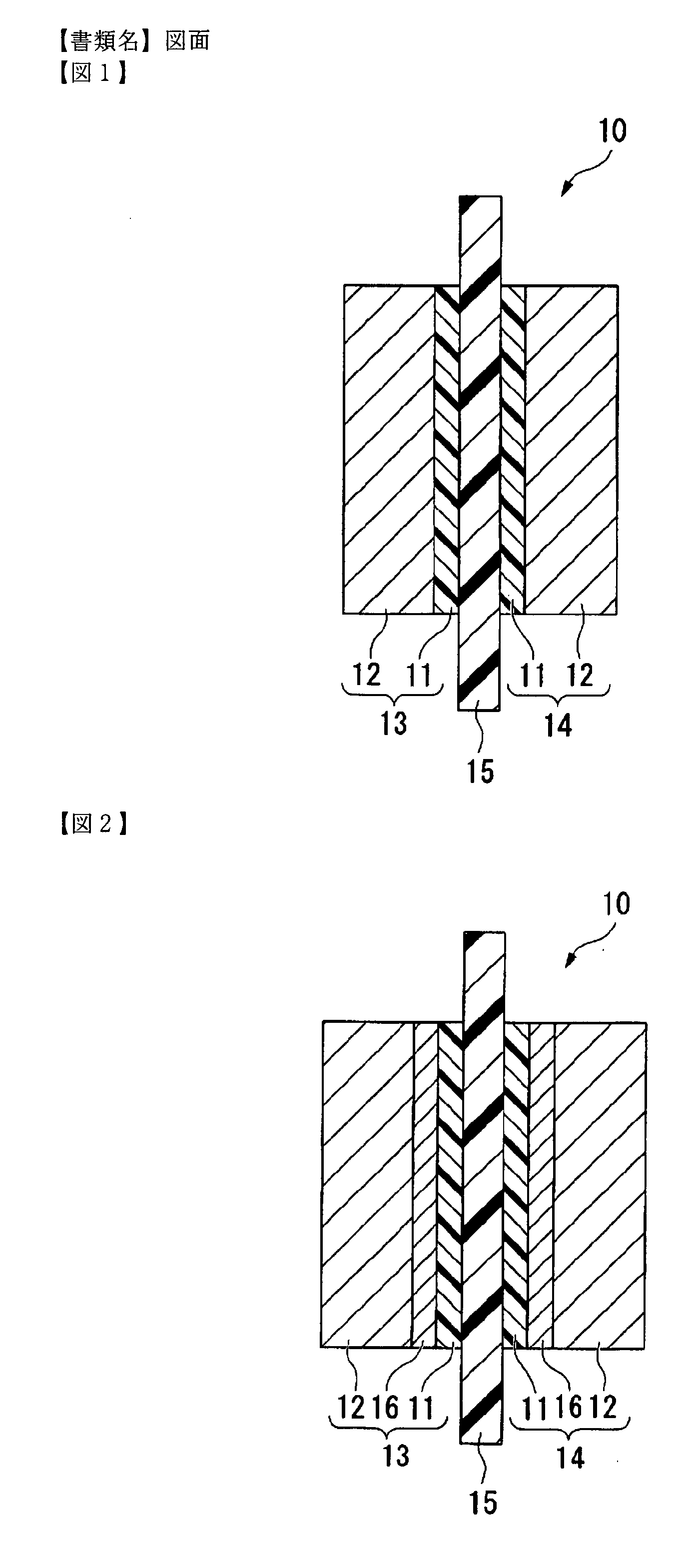
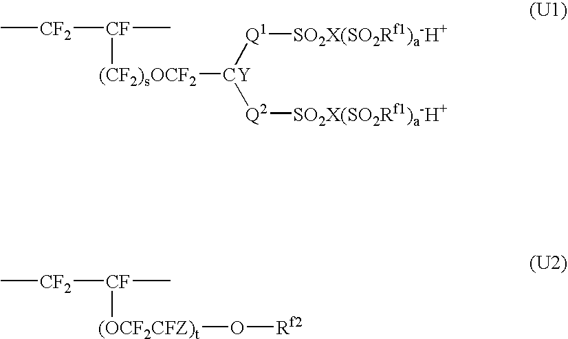
A polymer electrolyte membrane made of a polymer has a low electrical resistance, high heat resistance and is strong against repeats of swelling and shrinkage. Thus, a membrane / electrode assembly for polymer electrolyte fuel cells having high power generation performance and excellent in durability can be provided.For a polymer electrolyte membrane 15 or for a catalyst layer 11 constituting electrodes 13 and 14, a polymer comprising units (U1) and units (U2) is used:Q1, Q2: a perfluoroalkylene group which may have —O— or the like; Rf1, Rf2: a perfluoroalkyl group which may have —O—; X: an oxygen atom or the like; a: 0 or the like; Y, Z: a fluorine atom, or a monovalent perfluoroorganic group such as —CF3; S: 0 to 1; and t: 0 to 3.

Description

BACKGROUND OF THE INVENTION[0001]1. Field of the Invention[0002]The present invention relates to a polymer, a polymer electrolyte membrane for polymer electrolyte fuel cells, and a membrane / electrode assembly.[0003]2. Discussion of Background[0004]A polymer electrolyte fuel cell is, for example, a stack of a plurality of cells each comprising a membrane / electrode assembly sandwiched between two separators. The membrane / electrode assembly comprises an anode and a cathode each having a catalyst layer and a polymer electrolyte membrane disposed between the anode and the cathode.[0005]As a polymer to be used for the polymer electrolyte membrane, the following polymer has been widely used.[0006](1) A polymer obtained by subjecting a copolymer of a monomer represented by the following formula and tetrafluoroethylene to conversion to an acid form to convert —SO2F groups to sulfonic acid groups (Non-Patent Document 1):CF2═CF—(OCF2CF(CF3))m—O—(CF2)n—SO2Fwherein m is an integer of from 0 to 1...

Claims


Application Information

Patent Timeline
Patent Type & Authority Applications(United States)
IPC IPC(8): H01M8/10C08F12/30C08J5/22
CPCC08J5/225C08J2327/12H01M8/1002Y02E60/521H01M8/1039H01M8/1067H01M2300/0082H01M8/1023H01M8/1007Y02E60/50
Inventor SHIMOHIRA, TETSUJIHAMAZAKI, KAZUOSAITO, SUSUMUHOMMURA, SATORUKOTERA, SEIGO
Owner ASAHI GLASS CO LTD
Why Eureka
Try Eureka