Fluidic array devices and systems, and related methods of use and manufacturing

a technology of fluidic arrays and array platforms, applied in the direction of machines/engines, ceramic shaping cores, chemical/physical processes, etc., can solve the problems of affecting the quality of the array, the current process for manufacturing both array platforms, and the inability to meet the needs of the customer, so as to eliminate possible contamination, facilitate the immobilization of the probe and the configuration of the spot, and facilitate the effect of configuration

Inactive Publication Date: 2008-08-28
HUANG JOSEPH ZHILI +2
View PDF13 Cites 8 Cited by
  • Summary
  • Abstract
  • Description
  • Claims
  • Application Information

AI Technical Summary

Benefits of technology

[0031]Advantages of embodiment fluidic array devices include flexibility and customization of the array devices. With sophisticated fluidic channels, intersection spots, and the fluidic interface, probe immobilization and configurations for the spots can be performed easily. For example, cystic fibrosis is one of the most common autosomal-recessive disorders, affecting one in 2500 births in the Caucasian population. Although over 1000 mutations have been identified that cause cystic fibrosis, only 25 have been generally recommended for carrier screening. But for different racial groups, the recommended mutations may be somewhat different. With embodiment fluidic array devices, the mutations detected for different racial groups can be easily configured in the array device. As new target variations arise, assays for them can be rapidly integrated into the fluidic array device.
[0032]A further advantage of various embodiments is that all liquid manipulations may occur inside the fluidic device. Probe coupling and target delivery may be done within the fluidic channels, which eliminates possible contamination and reduces requirements upon the operational environment, such as temperature, humidity, and airborne particulates. Failures resulting from human intervention are reduced to a minimum. Environmental contaminants may be completely eliminated.
[0033]Yet another advantage provided by certain embodiments is parallel detection of different samples and controls simultaneously with the same or different molecular probes under identical conditions. For example, in gene screening analysis, it is common that mutant-type, wild-type, and negative control samples are detected. With an embodiment fluidic array device, the same type of probes can be immobilized at the intersection spots, as provided by the fluidic interfaces, along the probe fluidic channel; and different samples and controls can be loaded into the different sample channels, and reacted with the probes along the sample channel. The reaction of the different samples and controls can be performed simultaneously under the same conditions. Target analysis on the same device at the same time makes sample comparisons and quality cont

Problems solved by technology

Currently, there are major drawbacks with microarray technologies.
Current processes for manufacturing both array platforms fail to allow for cost-effective customization.
Each spot on a microarray requires a discrete deposition or synthesis, both of which are subject to process variation and product control issues that add to the expense and time required for completion.
Although microarray and/or alternative approaches permit the measurement of tens of thousands of biological probes simultaneously, they can test only one biological sample at time.
This feature is ideal for genome-wide expression profiling, or SNP or protein screening, but is not ideal for applications where a limited number of genes or proteins will be examined for diagnostic purposes, and where testing multiple clinical samples at the same time is preferred.
In microfluidics, traditional materials, such as silicon and glass, are not always the best choice.
Realization of such structures generally requires multiple lithographic masking and etching, alignment and bonding steps, which add significant process complex

Method used


Image

  • Fluidic array devices and systems, and related methods of use and manufacturing
  • Fluidic array devices and systems, and related methods of use and manufacturing
  • Fluidic array devices and systems, and related methods of use and manufacturing

Examples


example embodiments

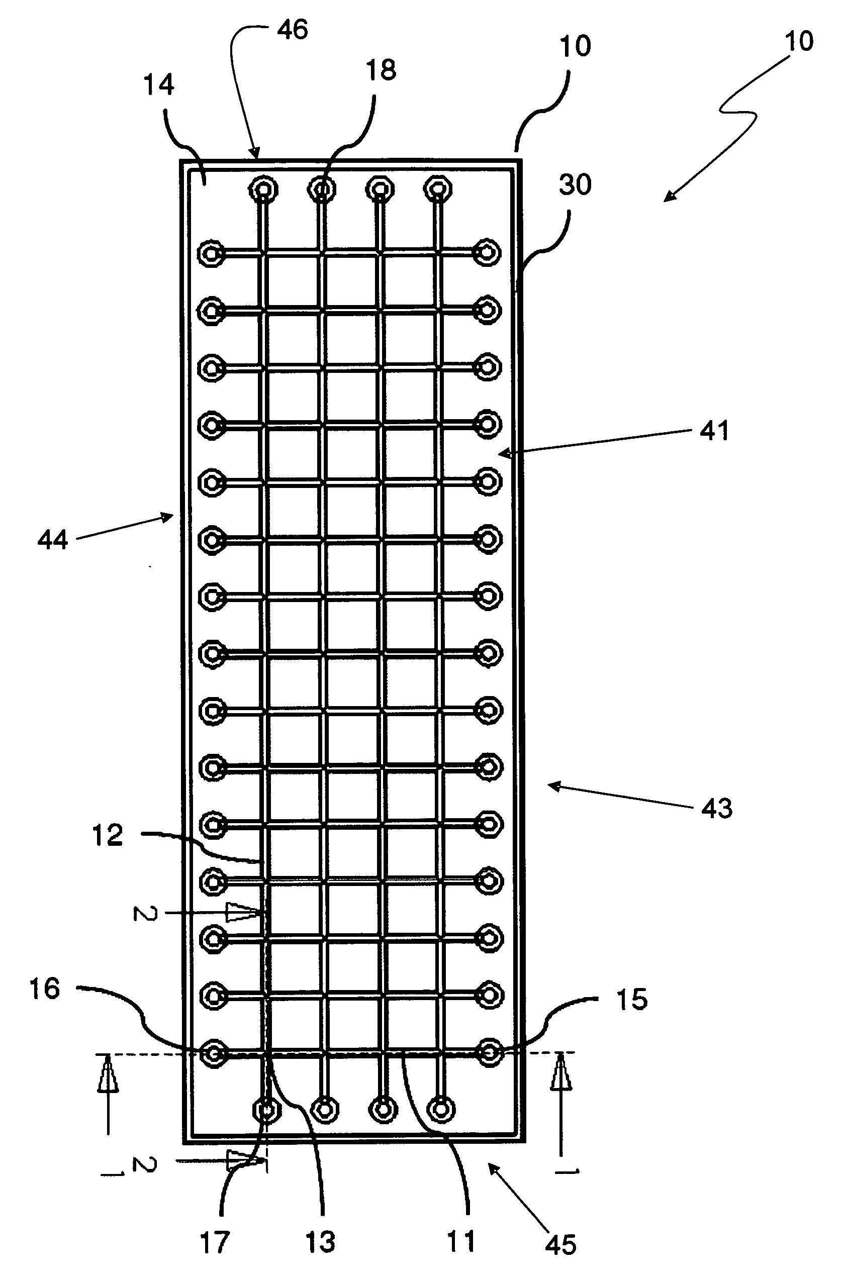
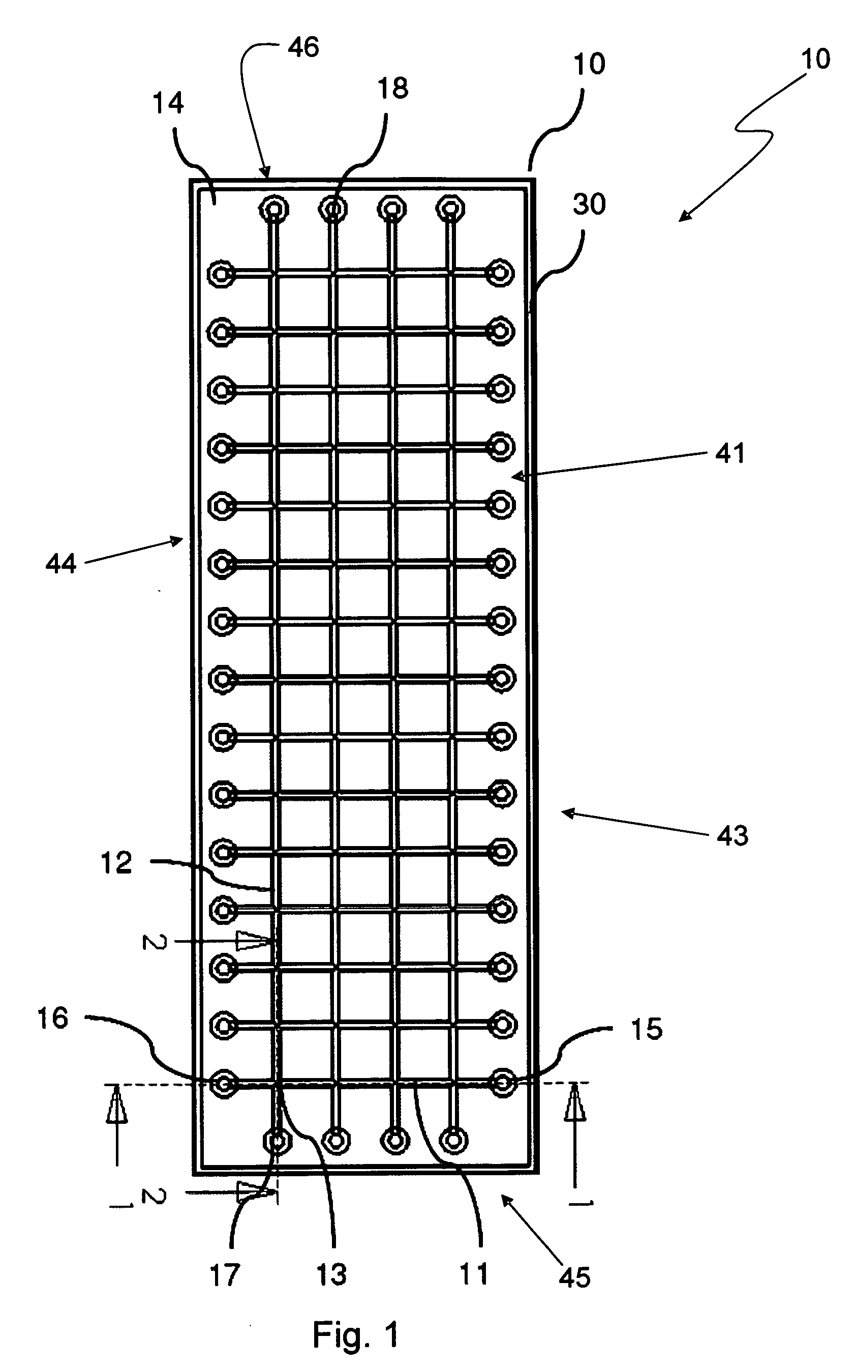
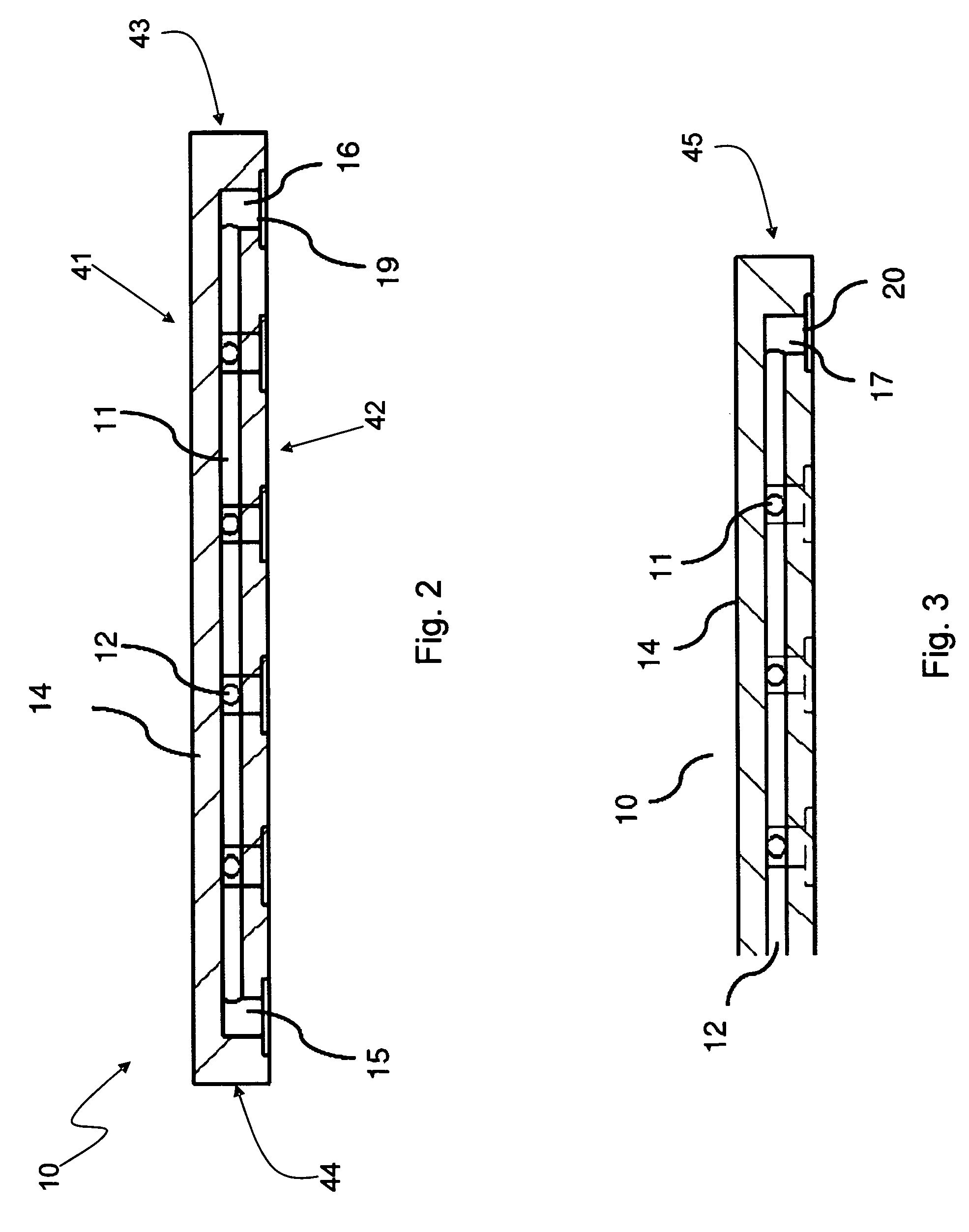
[0074]Various embodiments provide fluidic array devices, which may be used for chemical and biochemical analysis. FIG. 1 shows a top view of an embodiment fluidic array device 10 with a 4 15 array of intersection spots 13. FIG. 2 shows a sectional view of the array device 10 along a plan 1 indicated in FIG. 1. FIG. 3 shows another sectional view along a plan 2 indicated in FIG. 1.

[0075]The fluidic array device 10 includes a body 14. Inside the body 14 are four column fluidic channels 12 with fluidic interfaces 17 and 18, and fifteen row fluidic channels 11 with fluidic interfaces 15 and 16, which together form the 4 by 15 array of intersection spots 13 by respective intersections of column fluidic channels 12 with row fluidic channels 11. The body 14 of the device 10 may be made of an elastomeric material by any suitable molding process, such as by a molding process disclosed in U.S. Pat. No. 7,125,510 to Zhili Huang, entitled “Microstructure Fabrication and Microsystem Integration,...

modification example

SURFACE NANOENGINEERING MODIFICATION EXAMPLE

[0106]Nanofabrication opens a new window for microfluidics. FIG. 15 shows a perspective view of one intersection spot 520 at an intersection of two channels in another embodiment fluidic array device 500. FIG. 16 is a sectional view of the device 500 shown in FIG. 15. The device 500 includes a body 502, which may be similar to the elastomeric bodies described above. Inside the body 502, a fluidic channel 504 and a fluidic channel 506 intersect to form the intersection spot 520. The fluidic channels 504, 506 may be, for example, rectangular with an aspect ratio from 1:5 to 1:1000. The respective top surfaces 508 and 516 and bottom surfaces 510 and 518 of the fluidic channel 504 and 506 can be nanoengineered to obtain certain surface wetting properties, while the top surface 512 and the bottom surface 514 at the intersection spot 520 can be nanoengineered to another surface wetting property. The fluidic channels 504 and 506 can be closed at ...


PUM

PropertyMeasurementUnit
Thicknessaaaaaaaaaa
Elastomericaaaaaaaaaa
Structureaaaaaaaaaa

Abstract

The instant application provides a fluidic array device having an elastomeric body that provides easy fluidic control of the device. The elastomeric body may include plurality of intersecting row and column channels. Reactions may occur at the intersection spots formed by the intersecting channels. Pinching applied at suitable locations along the channels enables the channels to be opened or closed, and thus provides control of fluids pumped through the device. The surfaces of the channels and intersection spots may be engineered to have certain properties. In particular, the intersection spots may be nanoengineered to have surface properties differing from those of the channels, and thus reactions may be selectively controlled to occur only, or highly preferentially, in the intersection spots.

Description

CROSS-REFERENCE TO RELATED APPLICATIONS[0001]This application claims the benefit of U.S. Provisional Patent Application No. 60 / 971,886, filed on Sep. 12, 2007 and of U.S. Provisional Patent Application No. 60 / 891,347, filed on Feb. 23, 2007, both of which are incorporated herein by reference.FIELD OF THE INVENTION[0002]This invention relates to fluidic array devices and instruments with channels and fluidic interfaces, controls of fluid flow within the channels in the device, methods for chemistry or biochemistry probe coupling and reactions, and applications in chemistry and biochemistry, and clinical diagnosis. This invention also relates to fluidic array devices with nanoengineered channel surfaces, and / or embedded materials to immobilize DNA, proteins, cells, and / or other chemicals or molecules for biochemical or biological analysis, and methods for making such devices.BACKGROUND OF THE INVENTION[0003]Microarray Biochip technologies have become central platforms for biological r...

Claims


Application Information

Patent Timeline
IPC IPC(8): B01J19/00B29C39/00B01L9/00
CPCB01L3/5027Y10T436/25B01L3/50273B01L3/502738B01L9/527B01L2200/12B01L2300/0636B01L2300/0816B01L2300/0896B01L2300/123B01L2300/166B01L2400/0406B01L2400/043B29C39/006B82Y30/00Y10T436/11Y10T436/2575B01L3/502715Y10T137/7761
Inventor HUANG, JOSEPH ZHILISHI, YONGMA, YUFENG
Owner HUANG JOSEPH ZHILI
Why Eureka
Try Eureka