Graded Spin-on Organic Antireflective Coating for Photolithography

a technology of organic antireflective coating and spin-casting, which is applied in the direction of photosensitive materials, instruments, photomechanical equipment, etc., can solve the problems of non-uniform photoresist linewidth upon development, deterioration of printed image quality, and variation of linewidth

Active Publication Date: 2008-09-04
GLOBALFOUNDRIES U S INC
View PDF20 Cites 14 Cited by
  • Summary
  • Abstract
  • Description
  • Claims
  • Application Information

AI Technical Summary

Benefits of technology

[0018]The present disclosure provides an improved process for lithographic imaging, and especially at high NA, and in particular where highly reflective substrates are utilized, or when embedded topography is present in the semiconductor substrate.
[0019]The present disclosure comprises the formation and use of a single-layer spin-on graded BARC having strategically designed optical qualities. The optical properties qualities make possible the enhancement of the control of design features below 65 nm.

Problems solved by technology

However, when photoresists are exposed on reflective substrates in the presence of underlying surface topography, critical dimension (CD) control problems are exacerbated under high NA imaging conditions, and lead to the deterioration of the quality of the printed image.
Reflection of light from the substrate / resist interface produces variations in the light intensity and scattering in the resist during exposure, resulting in non-uniform photoresist linewidth upon development.
Light can scatter from the interface into regions of the resist where exposure was not intended, resulting in linewidth variations.
The amount of scattering and reflection will typically vary from region to region resulting in linewidth non-uniformity.
Unfortunately, due to resist / substrate interface reflections, constructive and destructive interference is particularly significant when monochromatic or quasi-monochromatic light is used for photoresist exposure.
In such cases the reflected light interferes with the incident light to form standing waves within the resist.
In the case of highly reflective substrate regions, the problem is exacerbated since large amplitude standing waves create thin layers of underexposed resist at the wave minima.
If the resist thickness is non-uniform, the problem becomes more severe, resulting in variable linewidth control.
This deviation from normal incidence causes increased reflectance at the resist-air and resist-substrate interfaces, thus exacerbating the problem.
In addition to the challenges posed by the use of high NA optical systems described above, additional difficulties arise in this field due to the fundamental loss in image contrast that occurs for the transverse magnetic (TM or p-) polarization state at large oblique angles (T. Brunner et al., Proceedings of SPIE Vol. 4691, p.
This loss in TM image contrast at high angles adds up to other sources of image contrast degradation such as blocking of diffraction orders at the pupil edge, defocus effects, image flare effects, stage vibrations, etc.
Linewidth control problems due to non-uniform reflectance also arise from substrate topography.
Any image on the wafer will cause impinging light to scatter or reflect in various uncontrolled directions (reflective notching), affecting the uniformity of resist development.
A top ARC (TARC) deposited over the photoresist layer can significantly reduce the swing effect by reducing the reflectivity at the air-photoresist interface, However a TARC does not reduce the notching problem.

Method used


Image

  • Graded Spin-on Organic Antireflective Coating for Photolithography
  • Graded Spin-on Organic Antireflective Coating for Photolithography
  • Graded Spin-on Organic Antireflective Coating for Photolithography

Examples


example 1

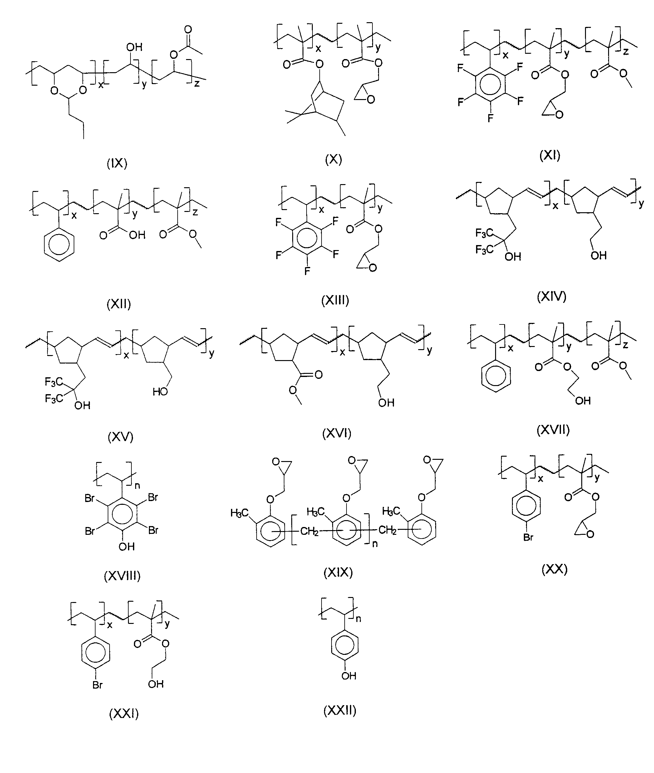
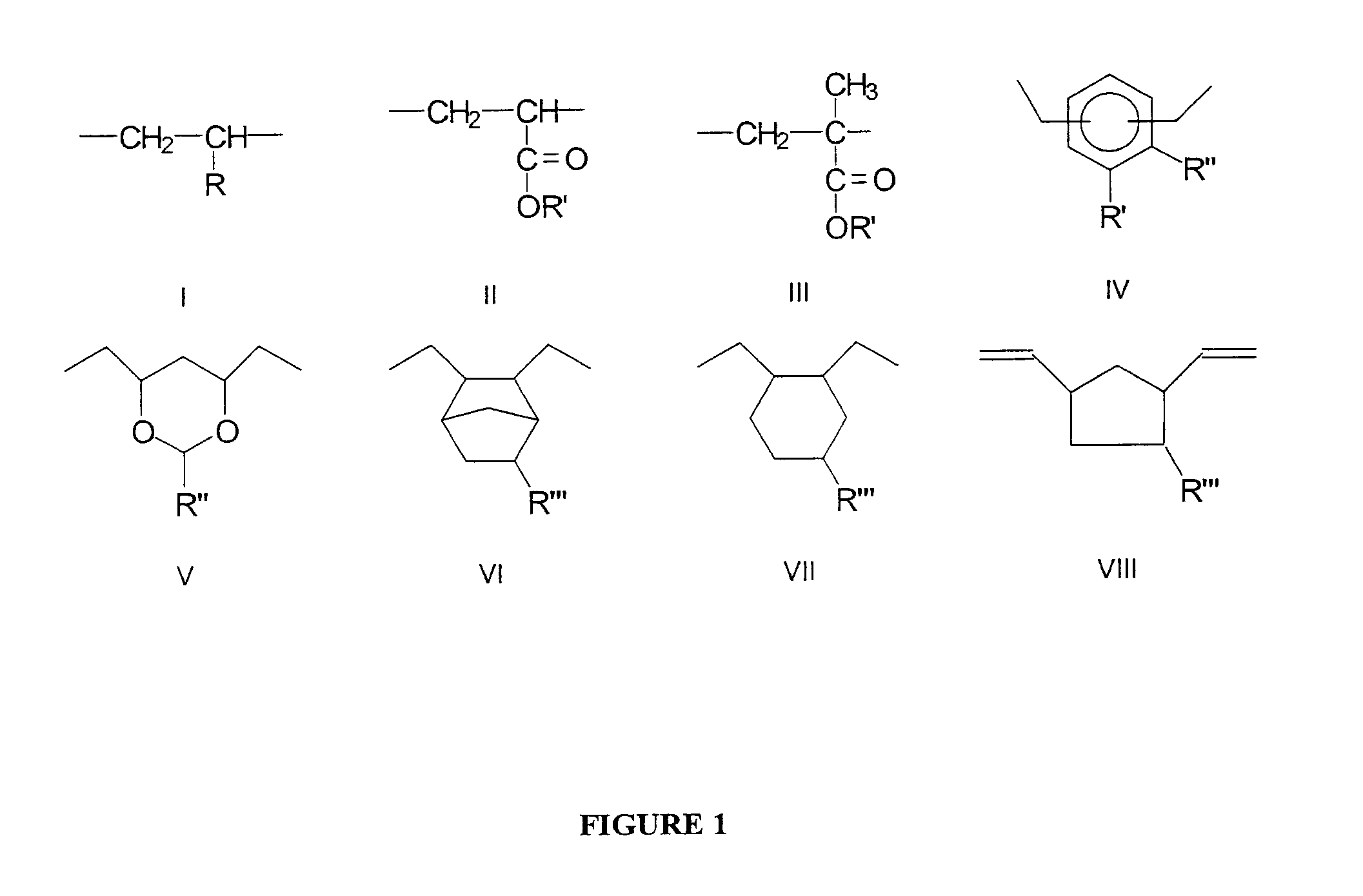
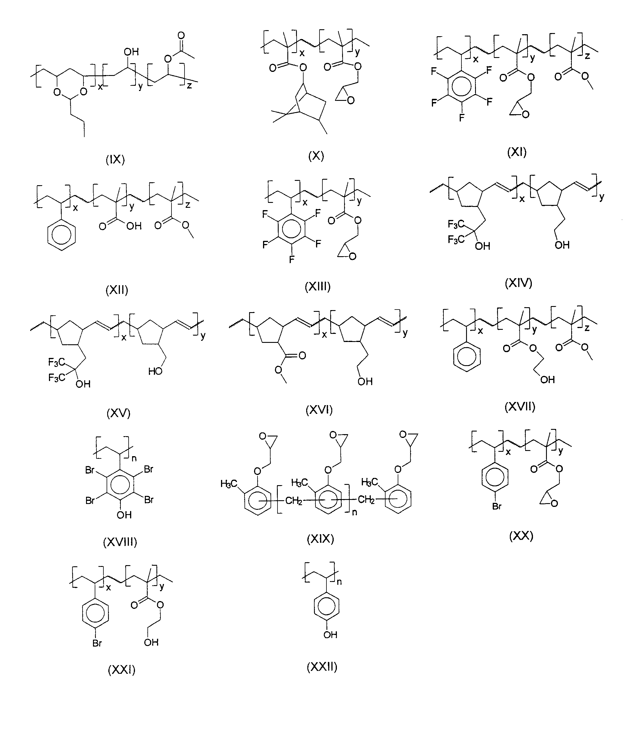
[0082]Materials Synthesis (Polymer H)— Grubbs catalyst, 2nd generation (0.02 mmol, 17 mg) is dissolved in tetrahydrofuran THF (10 mL) under nitrogen atmosphere at 60° C. and allyl acetate (1 mmol, 0.1 g) is added followed by a THF solution (5 mL) of the norbornene monomers: 5-norbornene-2-methanol (5 mmol, 0.62 g) and 5-norbornene-2-yl-1,1-bistrifluoromethylethanol (5 mmol, 1.37 g). The reaction mixture is stirred at 60° C. for about 18 hours. Then isobutyl- or ethyl-vinyl ether is added (1 mL) and the reaction is allowed to cool for 30 minutes. Addition of hexane causes the polymer to separate as a thick oil that is decanted and washed with more hexane. Vacuum drying at 50° C. overnight affords the desired polymer product as an off-white crystalline-looking powder. Yield is 60-100%.

[0083]Materials Synthesis (Polymer O, PolyhydroxyStyrene—weight average molecular weight 8000)—A standard procedure reported in the literature (G. Barclay et al., Proceedings of SPIE, Vol. 2724, p. 249, ...

example 2

[0084]Optical and Physical Properties—The optical constants (the index of refraction n and the extinction coefficient k) of individual components suitable for graded BARC applications are measured at a radiation wavelength of 193 nm using a Variable Angle Spectroscopic Ellipsometer (VASE) manufactured by J. A. Woollam, Inc. The optical properties of individual polymer components are shown in FIG. 3:

example 3

[0085]Formulation—Polymer components H and O are dissolved in propylene glycol monomethyl ether acetate (PGMEA) in individual concentrations of 50 parts by weight each (1.8% by weight each with respect to the solvent). One polymer component has an extinction coefficient k higher than 0.5. Another polymer component has an extinction coefficient k lower than 0.5. A crosslinking agent tetramethoxymethyl glycoluril, available from DayChem, in a concentration of 10 parts by weight and di(t-butylphenyl)iodonium perfluorobutylsulfonate (DtBPI—PFBuS) in a concentration of 5 parts by weight are added to the solution, achieving 4.2 wt. % by weight of total solids.


PUM

PropertyMeasurementUnit
thicknessaaaaaaaaaa
thicknessaaaaaaaaaa
refractive indexaaaaaaaaaa

Abstract

An antireflective coating that contains at least two polymer components and comprises chromophore moieties and transparent moieties is provided. The antireflective coating is useful for providing a single-layer composite graded antireflective coating formed beneath a photoresist layer.

Description

CROSS REFERENCE TO RELATED APPLICATIONS[0001]This application is a Divisional of co-pending application Ser. No. 11 / 473,338, filed on Jun. 23, 2006, and for which priority is claimed under 35 U.S.C. §120; the entire contents of all are hereby incorporated by referenceTECHNICAL FIELD[0002]The present disclosure relates to polymer compositions and their use in photolithography including deep ultraviolet photolithography and semiconductor fabrication. More specifically, a spin-castable multi-component organic antireflective coating (ARC) is disclosed wherein the materials composition is varied throughout the thickness of the ARC layer such that the complex refractive index of the graded ARC layer varies from the ARC-substrate interface to the ARC-photoresist interface. As a result, the radiation intensity that is reflected at the ARC-photoresist interface is substantially decreased, while the light that penetrates the ARC layer is absorbed, thus minimizing the radiation reflected from ...

Claims


Application Information

Patent Timeline
Patent Type & Authority Applications(United States)
IPC IPC(8): G03F1/14
CPCG03F7/091Y10S438/952
Inventor BRODSKY, COLIN J.BURNS, SEAN D.GOLDFARB, DARIO L.LERCEL, MICHAELMEDEIROS, DAVID R.PFEIFFER, DIRKSANDERS, DANIEL P.SCHEER, STEVEN A.VYKLICKY, LIBOR
Owner GLOBALFOUNDRIES U S INC
Why Eureka
Try Eureka