Plasmon energy converter

a technology of energy converter and plasmon, applied in the field of energy converter, can solve the problems of increasing interference or crosstalk between detectors, reducing the efficiency of detectors at absorbing specific wavelengths of electromagnetic energy, and contributing to noise or output signal degradation, etc., to achieve the effect of facilitating coupling incident electromagnetic energy

Inactive Publication Date: 2008-09-11
TANNER RES
View PDF3 Cites 41 Cited by
  • Summary
  • Abstract
  • Description
  • Claims
  • Application Information

AI Technical Summary

Benefits of technology

[0015]The novel design of certain embodiments discussed herein is facilitated by use of plasmons to facilitate coupling incident electromagnetic energy into an electrical signal. The plasmons may be manipulated to enable use of smaller detector elements; to focus and confine energy into low-noise regions of an accompanying detector element; to enable adjustments in detector sensitivity to wavelength, incident angle, and polarization, without the need for expensive filters or optics; and so on.

Problems solved by technology

Unfortunately, certain electron-hole pairs are generated via heat or other processes, and certain electron-hole pairs spontaneously combine.
These processes contribute to noise or output signal degradation.
Unfortunately, as the size and spacing between detectors in an array decrease, the detectors may become less efficient at absorbing specific wavelengths of electromagnetic energy.
Furthermore, interference or crosstalk between detectors may increase.
Such factors have limited minimum detector sizes.
Unfortunately, large detectors may undesirably limit resolution of accompanying imaging systems.
However, such mechanisms are often prohibitively expensive and may introduce undesirable artifacts in the resulting array output.

Method used


Image

  • Plasmon energy converter
  • Plasmon energy converter
  • Plasmon energy converter

Examples


fourth embodiment

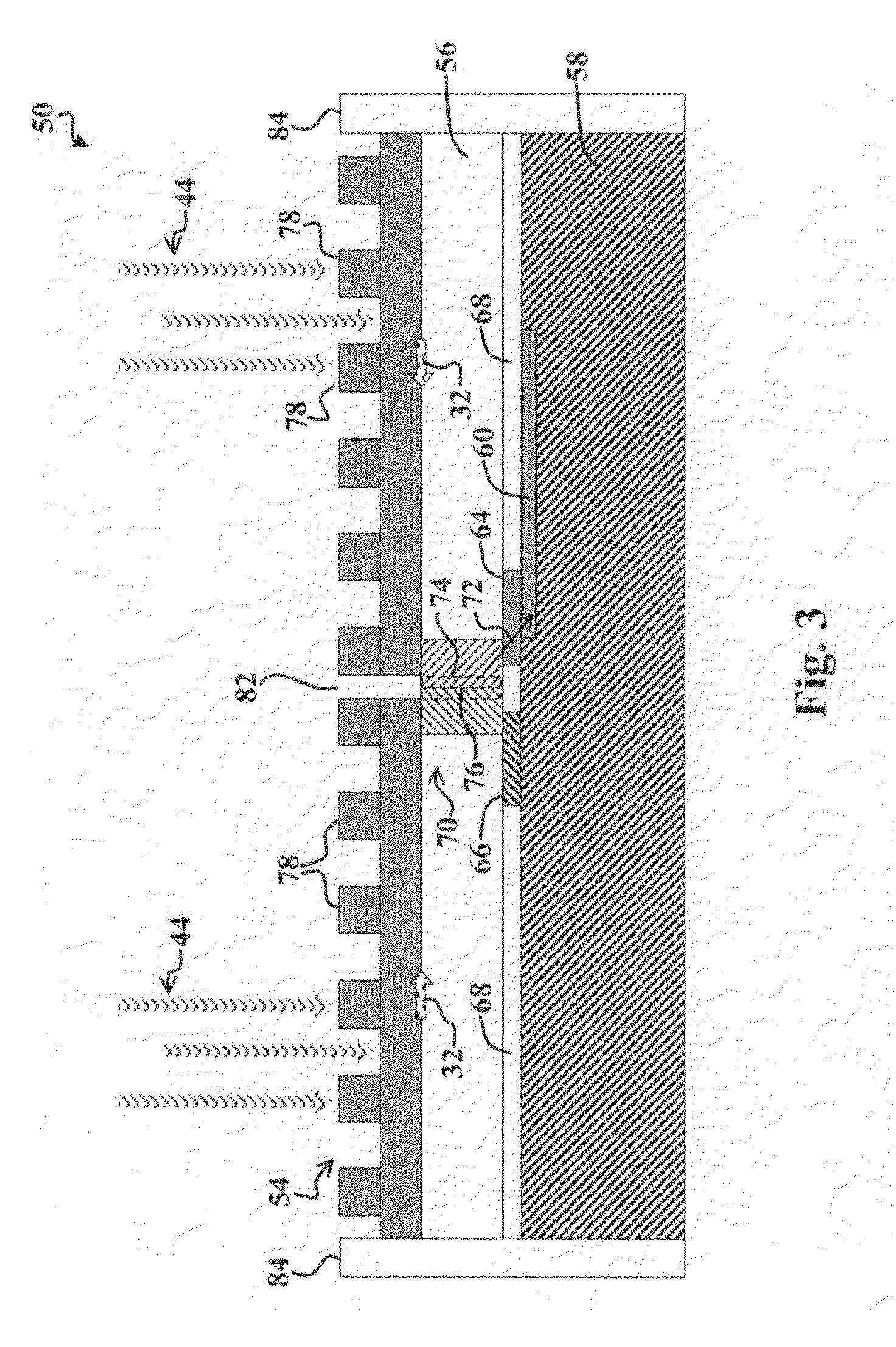
[0092]FIG. 7 is a cross-sectional diagram of a detector 140 adjusted for sensitivity to a particular wavelength of electromagnetic energy according to the present invention. The detector 140 includes a wavelength-tuned grating 142, with slots 152 cut therein to cause the detector 140 to be responsive to a certain wavelength of incident energy. The grating 142 is isolated from a p-type substrate 146 via an insulating spacer 150. Between the spacer 150, the grating 142 contacts an n-type region 144 formed in the substrate 146. The interface between the n-type region 144 and the p-type region 154 represents a pn-junction, in which an active region forms 154 during conversion of plasmons to electrical current. The detector 140 is partially surrounded by a plasmon reflector 84.

[0093]A central perforation 156 in the grating 142 opens above the n-type-region 144, and acts to confine the generation of electron-hole pairs to the n-type-region of the detector 140. This focusing and confinemen...

fifth embodiment

[0094]FIG. 8 is a top view of a superpixel 160, according to the present invention, which includes different detectors 140, 162, 164, which are tuned for sensitivity to different wavelengths or ranges of wavelengths of incident electromagnetic energy. The tuning of wavelength sensitivity is achieved by adjusting the spacing between grating grooves 152, 162, 172. Similar sensitivity adjustments may be made by adjusting the aspect ratios of the slots or slots 152, 162, 172, as illustrated in the graph 120 of FIG. 6.

[0095]The superpixel 160 represents a group of pixels, with each pixel tuned for a specific wavelength or range of wavelengths of incident electromagnetic energy. In the example superpixel 160 of FIG. 8, shorter wavelengths of incident energy are selected by use of shorter spacings between the grooves or slots 152, 162, 172 in the grating material 142. Hence, the superpixel 160 may simultaneously detect light of three different wavelength bands. Note that superpixels includ...

sixth embodiment

[0103]FIG. 9 is a top view of an array 180 of superpixels according to the present invention.

[0104]In an imaging array of photodiodes or other energy detectors, the ultimate limit for pitch is governed by the wavelength of incident light, since a photodiode with dimensions less than the wavelength will be nearly transparent to the incident light. Use of the enhanced photodiode architecture described herein may significantly reduce the ultimate limit for photodiode pitch.

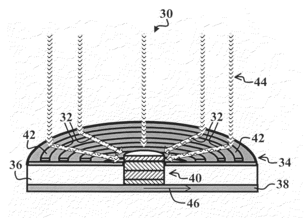
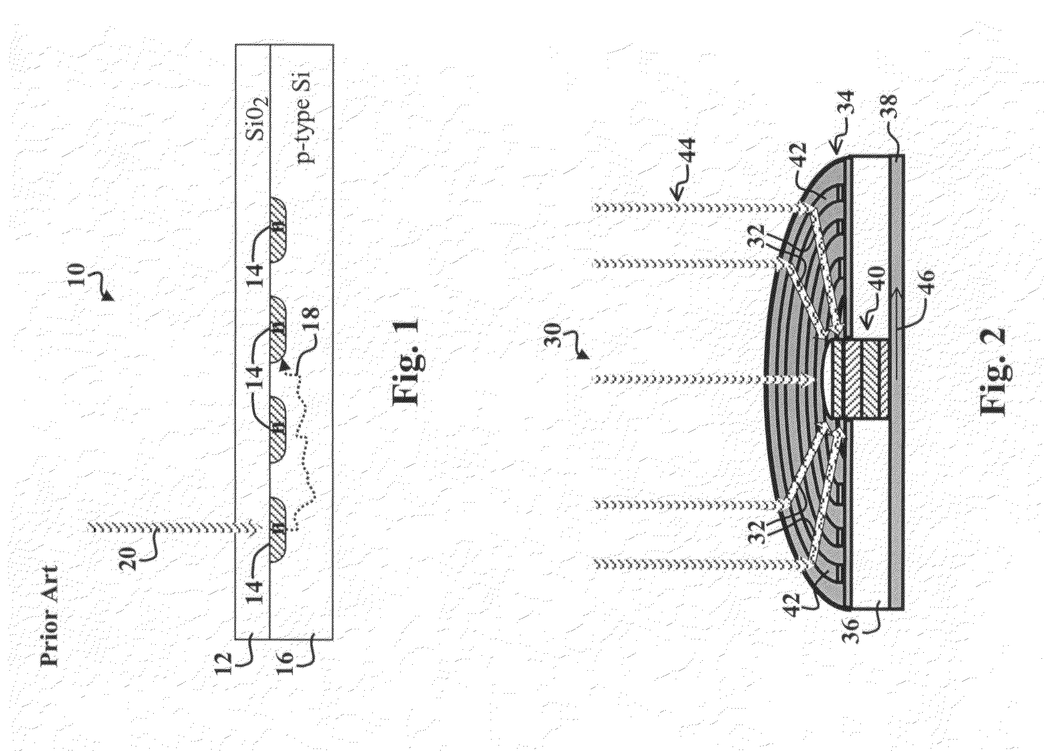
[0105]Photodiode pitch limitations are often influenced by several other factors. One of the critical factors is the diffusion length scale of the electron-hole pairs, as illustrated by the random path 18 shown in FIG. 1. In a typical photodiode, some of the incident light is absorbed outside the depletion region at the n / p interface. The resultant electron hole pairs can diffuse randomly in any direction; and will have a high likelihood of being collected at the electrodes for a neighboring pixel if the pixel pitch ...


PUM


Abstract

An energy converter employing plasmons. In a specific embodiment, a receiver receives a first type of energy or signal and provides one or more plasmons in response thereto. A detector is coupled to the receiver. The detector converts the one or more plasmons into a second type of energy or signal. In a more specific embodiment, the first type of energy or signal includes incident electromagnetic energy, such as visible, infrared, or ultraviolet radiation. The second type of energy or signal includes an electrical signal. The receiver includes a conductor grating that is coupled to a dielectric material. Examples of the detector includes a pn-junction and an interfacial bandgap junction. The receiver and the detector are coupled so that the one or more plasmons form a plasma wave as they travel from the receiver to the detector.

Description

CLAIM OF PRIORITY[0001]This invention claims priority from U.S. Provisional Patent Application Ser. No. 60 / 779,587, entitled ENHANCED PHOTODIODES WITH LENSING DUE TO EXTRAORDINARY TRANSMISSION, AND / OR SURFACE PLASMON / PHONON RESONANCE AND / OR RESONANT NANOHOLES, filed on Mar. 8, 2006, which is hereby incorporated by reference as if set forth in full in this specification.BACKGROUND OF THE INVENTION[0002]1. Field of Invention[0003]This invention relates to energy converters. Specifically, the present invention relates to devices, such as photodetectors, photoconductors, and arrays thereof, for converting incident electromagnetic energy into plasma waves and / or electrical signals.[0004]2. Description of the Related Art[0005]Energy detectors are employed in various demanding applications including digital cameras, missile-guidance systems, motion detectors, radar receivers, microwave dishes, and other types of antennas. Such applications often demand efficient detectors that can effectiv...

Claims


Application Information

Patent Timeline
Patent Type & Authority Applications(United States)
IPC IPC(8): G01T1/24G01J1/42
CPCH01L31/022408H01L31/0352H01L31/02327H01L31/1037H01L31/103
Inventor VERMA, RAVIBRONGERSMA, MARK LUITZEN
Owner TANNER RES
Why Eureka
Try Eureka