Reliant Thermal Barrier Coating System and Related Methods and Apparatus of Making the Same

a technology of thermal barrier coating and thermal barrier coating, which is applied in the direction of solid state diffusion coating, magnetic body, nuclear engineering, etc., can solve the problems of reducing the performance of the engine, limiting the average coating life, and failure of the components to be coated, etc., and achieves low capital cost, low cost, and low cost.

Active Publication Date: 2008-09-11
UNIV OF VIRGINIA ALUMNI PATENTS FOUND
View PDF3 Cites 68 Cited by
  • Summary
  • Abstract
  • Description
  • Claims
  • Application Information

AI Technical Summary

Benefits of technology

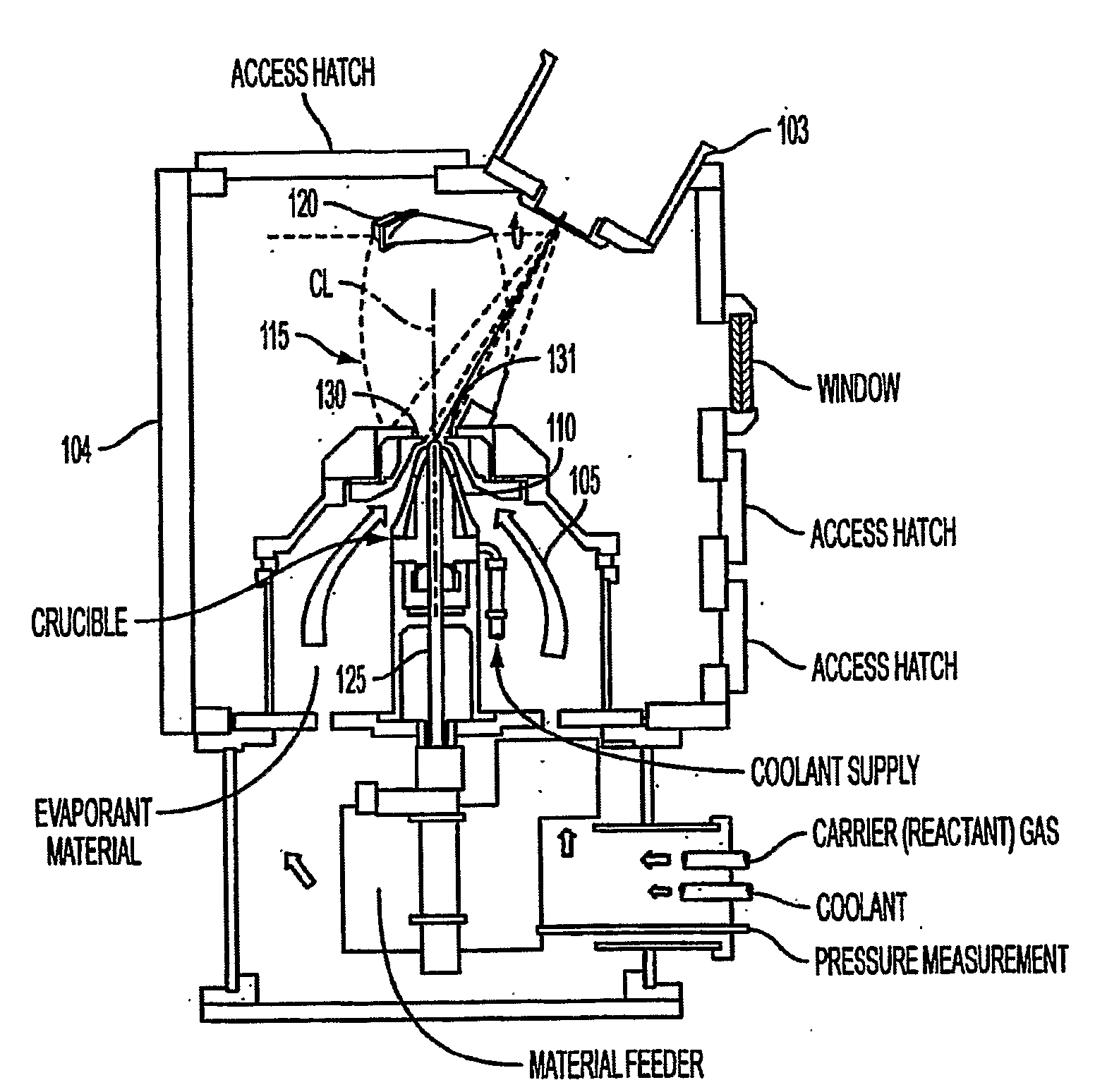
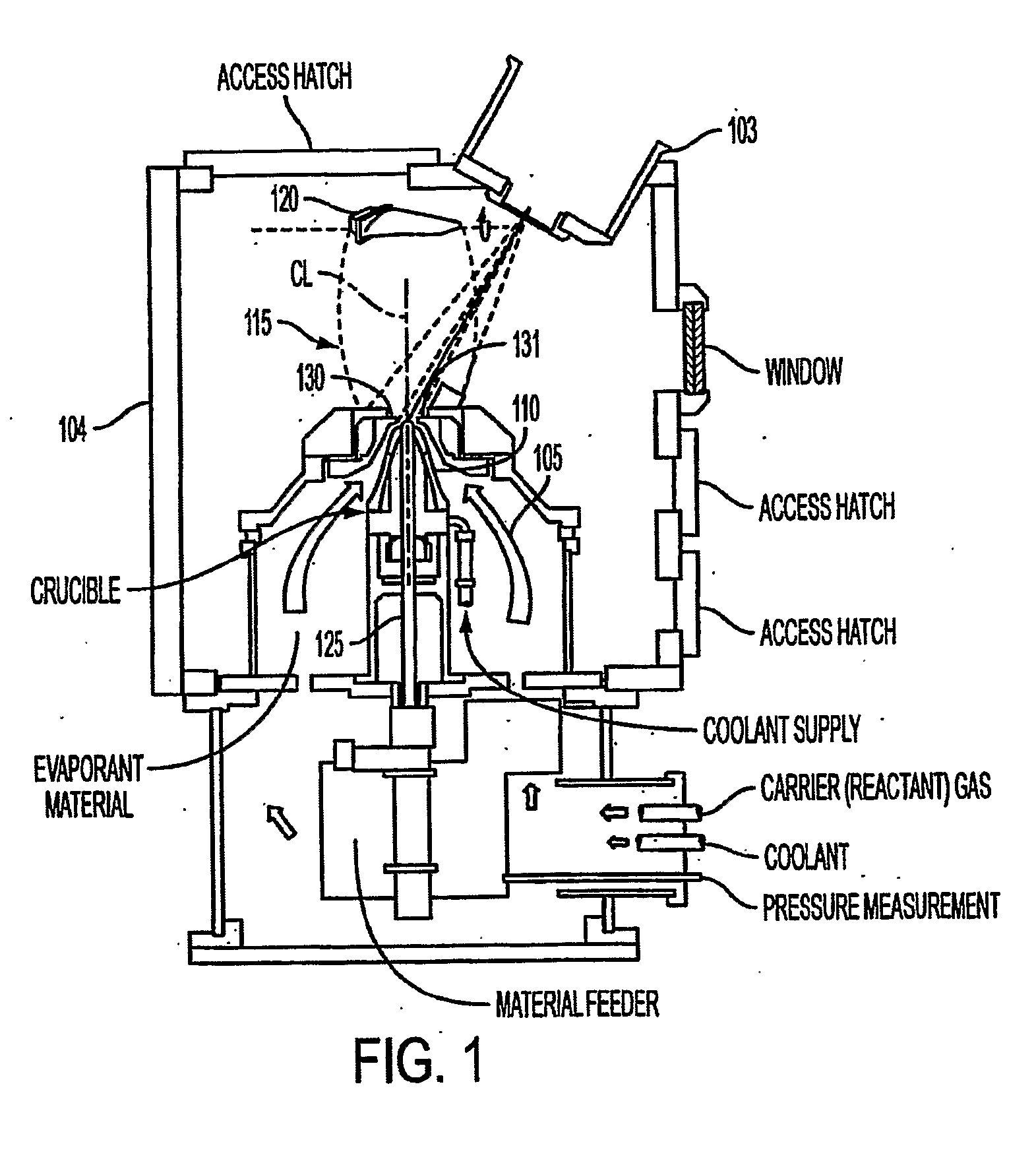
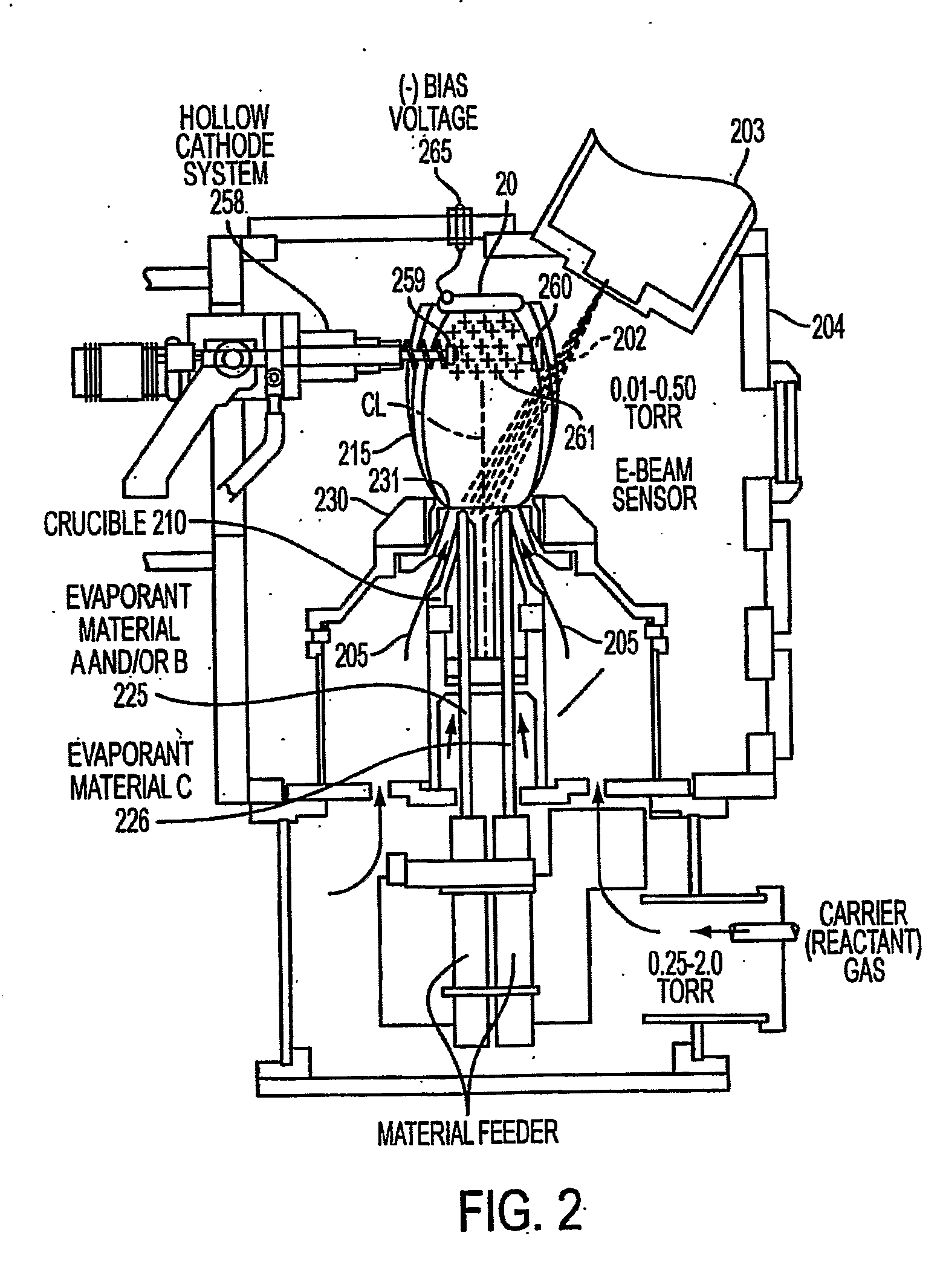
[0003]An aspect of various embodiments of the present invention provides, but not limited thereto, (i) a new multilayer coating architecture that will have robust performance in the cyclically loaded environments of engines and the like and (ii) a new process for malting (as well as related apparatus for making) either existing single bond+top coat layer systems or multilayered systems in a single deposition sequence within a single coating apparatus. This processing approach is also able to, among other things, “condition” the bond coating(s) surface to achieve a desired surface topology and aluminum (or other) oxide phase and spatial distribution. An aspect of various embodiments of the present invention will enable the deposition of thermal barrier coatings (TBCs) with a controlled interface between the bond coat and the top coat and a novel coating structure co...

Problems solved by technology

By insulating the metallic component, its temperature is reduced allowing it to last longer or to survive with less cooling air (cooling air reduces the performance of the engine).
Spallation, foreign object damage, ho...

Method used


Image

  • Reliant Thermal Barrier Coating System and Related Methods and Apparatus of Making the Same
  • Reliant Thermal Barrier Coating System and Related Methods and Apparatus of Making the Same
  • Reliant Thermal Barrier Coating System and Related Methods and Apparatus of Making the Same

Examples


Embodiment Construction

Thermal Barrier Coatings

[0026]The performance (fuel efficiency and thrust) of gas turbine engines is greatly improved as engine operating temperatures are increased. Similar improvements are seen for diesel engines. As a result, the hot structural components of these engines are designed to operate at very high temperatures, often approaching their melting point. As gas inlet temperatures have continued to rise, failure by thermally-induced mechanisms have been avoided through the development of higher temperature alloys, and for gas turbine engines by the emergence of directionally solidified and single crystal turbine blades, and by designing airfoil components with internal cooling conduits to allow injected compressor discharge air to decrease the component temperature. The use of cooling air, however, reduces engine efficiency and thus, it is desirable to minimize the use of this air for cooling purposes. All these approaches have now matured and alternate strategies that explo...


PUM

PropertyMeasurementUnit
Pressureaaaaaaaaaa
Pressureaaaaaaaaaa
Pressureaaaaaaaaaa

Abstract

A method and apparatus for forming a thermal barrier coating system (90) in communication with at least a portion of at least one substrate (92). The method includes: depositing a first bond coat (94) on at least a portion of at least one substrate (92); depositing a first thermal barrier coat (96) disposed on the bond coat (94); whereby the deposition occurs in one or more chambers to form the thermal barrier coating system (90); and wherein the deposition of the first bond coat (94) (or subsequent bond coats) and the deposition of the first thermal barrier coat (96) (or subsequent thermal barrier coats) is performed without out-of-chamber handling of the thermal barrier coating system (90).

Description

CROSS-REFERENCES TO RELATED APPLICATIONS[0001]The present application claims priority from U.S. Provisional Patent Application Ser. No. 60 / 695,348, filed Jun. 30, 2006, entitled “Prime Reliant Thermal Barrier Coating Concepts and Methods of Making the Same,” the entire disclosure of which is hereby incorporated by reference herein in its entirety.BACKGROUND OF THE INVENTION[0002]Thermal Barrier Coatings (TBCs) are used extensively in aircraft, marine and industrial gas turbine engines and in some diesel engines. They typically consist of a single metallic (or intermetallic) bond coat and a single ceramic top coat. The bond coat is made from a high aluminum content alloy such as NiAl modified with platinum and / or rare earth elements or a NiCoCrAlY alloy is used to provide oxidation and hot corrosion protection of the substrate (which is usually a nickel or cobalt based superalloy) and to promote the growth of an alpha aluminum oxide thermally grown oxide (TGO) which has high adhesion...

Claims


Application Information

Patent Timeline
IPC IPC(8): B05D1/08C23C14/30H05H1/24C23C14/34B05D1/36C23C16/44B29C35/08
CPCC23C14/0021C23C14/024C23C14/08Y02T50/67C23C14/30C23C14/325C23C14/228Y02T50/60
Inventor HASS, DEREK D.WADLEY, HAYDN N.G.
Owner UNIV OF VIRGINIA ALUMNI PATENTS FOUND
Why Eureka
Try Eureka