
Carbon Fibrous Conjunct and Composite Material Using Thereof

a technology of carbon fiber and conjunct, which is applied in the direction of metal/metal-oxide/metal-hydroxide catalyst, cell component, physical/chemical process catalyst, etc., can solve the problem of increasing and becoming a big problem, affecting the mechanical strength of the material obtained, and affecting the mechanical strength of the material. , to achieve the effect of good electrical conductivity, high density and high strength

Inactive Publication Date: 2008-10-16
HODOGOYA CHEMICAL CO LTD
View PDF6 Cites 114 Cited by
  • Summary
  • Abstract
  • Description
  • Claims
  • Application Information

AI Technical Summary

Benefits of technology

The invention is about a new carbon fiber composite material that is excellent in conductivity and damping ability, which is important for various electronic devices. The material is made by combining fine carbon fibers with a binder, and can be used as a matrix material for structural or functional applications. The carbon fibers are expensive, and it is difficult to achieve high conductivity without compromising other properties. However, the use of carbon fiber aggregates can improve the dispersibility of the fibers in the resin matrix and enhance the conductivity without adding a large amount of fibers. The carbon fiber aggregates used in the invention have a high bulk density, which is not ideal for some applications.

Problems solved by technology

Incidentally, as various electronic devices' penetration increases, troubles such as electric wave hindrance that the noise which occurs from a certain electronic component has an influence on peripheral equipments, and malfunction by static electricity, increase and become a big problem.
When using a metallic fiber and metallic powder as the conductive filler, however, there is a fault that the material thus obtained is inferior to the corrosion resistance and also that it is difficult to get an ample mechanical strength.
When using a carbon fiber as the conductive filler, it is possible to attain a predetermined strength and elastic modulus at a relative high additive amount of the filler, but not to attain an ample electrical conductivity.
Unfortunately, to use the carbon fiber at an additive amount large enough to attain the predetermined conductivity will be followed by the deterioration of the properties intrinsically owned by the original high molecular material.
Because of such manufacturing process, the weight loss during the carbonization process and the delay for carbonization rate become high, and a conclusion deduced from the facts is that the carbon fiber is expensive.
On the other hand, however, such fine carbon fibers unfortunately show an aggregate state even just after their synthesis.
When the aggregate is used as-is, it would arrive at a conclusion that the dispersion of the fine carbon fibers does not progress very far, and thus the product obtained can not enjoy ample properties.
Thus, it can not satisfy the thirst for acquisition of an ideal additive which improves various characteristics of the matrix, such as electric conductivity, effectively at a minuscule dosage.
Since the fixing is performed by such a heat treatment after synthesis of the carbon fibers, the fixing force at the contacting points is weak, and the electrical properties of the carbon fibrous structure itself do not become so good.
When the carbon fibrous structures are added to a matrix such as resin, the carbon fibers fixed at the contacting points are easily detached from each other, and thus the structure as the carbon fiber structure is no longer maintained in the matrix.
Therefore, it is not possible to construct preferable conductive paths in the matrix which contribute good electrical properties to the matrix by a small additive amount.
Furthermore, when the binder is added in order to promote the fixing at the contacting points and undergoes carbonization, the fibers in the obtained fibrous structure would become large in the diameter thereof and possess inferior surface characteristics because the binder added is attached to the whole area of the fibers rather than a limited area of the contacting points.Patent Literature 1: Japanese Patent No. 2862578Patent Literature 2: Japanese Patent Unexamined Publication 2004-119386 (JP 2004-119386 A)

Method used

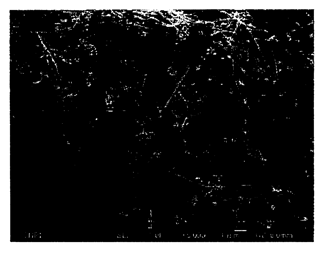
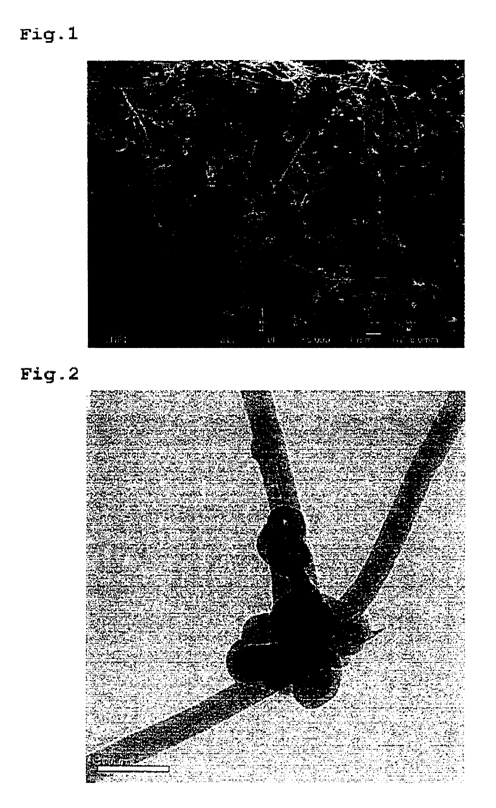
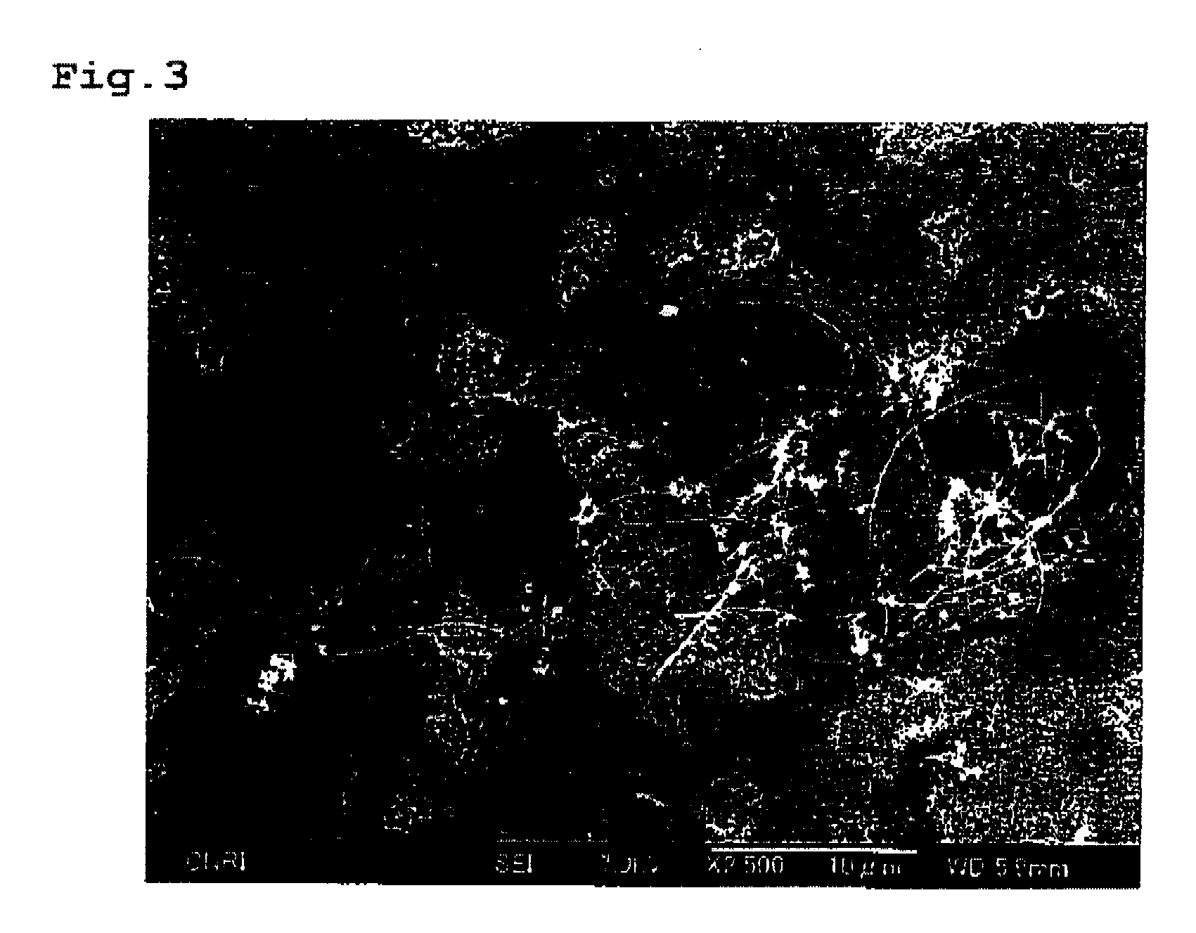

Image

  • Carbon Fibrous Conjunct and Composite Material Using Thereof
  • Carbon Fibrous Conjunct and Composite Material Using Thereof
  • Carbon Fibrous Conjunct and Composite Material Using Thereof

Examples


synthetic example 1

[0155]By the CVD process, carbon fibrous structures were synthesized from toluene as the raw material.

[0156]The synthesis was carried out in the presence of a mixture of ferrocene and thiophene as the catalyst, and under the reducing atmosphere of hydrogen gas. Toluene and the catalyst were heated to 380° C. along with the hydrogen gas, and then they were supplied to the generation furnace, and underwent thermal decomposition at 1250° C. in order to obtain the carbon fibrous structures (first intermediate).

[0157]The generation furnace used for the carbon fibrous structures (first intermediate) is illustrated schematically in FIG. 8. As shown in FIG. 8, the generation furnace 1 was equipped at the upper part thereof with a inlet nozzle 2 for introducing the raw material mixture gas comprising toluene, catalyst and hydrogen gas as aforementioned into the generation furnace 1. Further, at the outside of the inlet nozzle 2, a cylindrical-shaped collision member 3 was provided. The colli...

synthetic example 2

[0167]By the CVD process, carbon fibrous structures were synthesized using a part of the exhaust gas from the generation furnace as a recycling gas in order to use as the carbon source the carbon compounds such as methane, etc., included in the recycling gas, as well as a fresh toluene.

[0168]The synthesis was carried out in the presence of a mixture of ferrocene and thiophene as the catalyst, and under the reducing atmosphere of hydrogen gas. Toluene and the catalyst as a fresh raw material were heated to 380° C. along with the hydrogen gas in a preheat furnace, while a part of the exhaust gas taken out from the lower end of the generation furnace was used as a recycling gas. After it was adjusted to 380° C., it was mixed with the fresh raw material gas on the way of the supplying line for the fresh raw material to the generation furnace. The mixed gas was then supplied to the generation furnace.

[0169]The composition ratio in the recycling gas used were found to be CH4 7.5%, C6H6 0....

example 1

[0182]As raw materials, the fine carbon fibrous structures obtained from Synthetic Example 1, methanol, water, and methyl cellulose were mixed in a mixing ratio of carbon fibrous structures:methanol:water:methyl cellulose=20:20:9:1, and the resultant mixture was subjected to granulation by using a Vertical Granulator (manufactured by POWLEX Co., Ltd.) for 15 minutes. After the granulation, the prepared granules were dried at a temperature of not less than 100° C. in order to remove methanol and water. Thereby, granules of the carbon fibrous structures having a mean diameter of 500 μm were prepared.


PUM

PropertyMeasurementUnit
diameteraaaaaaaaaa
diameteraaaaaaaaaa
diameteraaaaaaaaaa

Abstract

Carbon fibrous conjunct is provided by adding to carbon fibrous structures, which each comprises a three dimensional network of carbon fibers each having an outside diameter of 15-100 nm, wherein the carbon fibrous structure further comprises a granular part with which the carbon fibers are bound in the state that the carbon fibers extend outwardly from the granular part, a binder for binding the carbon fibrous structures. The fine carbon fibrous structures having such unique configuration and also bearing physical properties suitable for a filler for a composite material can be provided with a good handleability by this carbon fibrous conjunct. Composite material is prepared by adding to the matrix the carbon fibrous conjuncts, at an amount of 0.1 to 30% by weight based on the total weight of the composite material.

Description

TECHNICAL FIELD[0001]This invention relates to a carbon fibrous conjunct which is composed of fine carbon fibrous structures each having a specific form and a binder, and also to a composite material in which the fine carbon fibrous conjuncts are combined with a matrix.BACKGROUND ART[0002]Heretofore, composite preparation with plural materials has been developed in order to attain a unique characteristic which has been never obtained by any single material. As a composite material, glass fiber reinforced plastic had been widely utilized. After carbon fibers and reinforced plastic using thereof (CFRP) has been developed, the composite material has particularly come into general use.[0003]These material has been widely used for sporting goods and so on, and come into focus as a light weight-, high intensity- and high elastic modulus-structural material for aircraft. Further, in addition to the fiber reinforced materials, minute particle reinforced materials have been also developed as...

Claims


Application Information

Patent Timeline
Patent Type & Authority Applications(United States)
IPC IPC(8): B32B5/00
CPCB01J23/745Y10T428/2918B01J37/086B82Y30/00C04B35/83C04B2235/526C04B2235/5264C04B2235/5436C04B2235/5481C08J5/005D01F9/127H01M4/587H01M4/625H01M8/0202H01M10/052H01M2004/021Y02E60/122H01G11/24Y02E60/13B02C19/0056C09J11/04Y10T428/30B01J35/0013Y02E60/50Y02E60/10B01J35/23D06M15/03D06M15/09
Inventor HANDA, KOICHISUBIANTORO, D.TSUKADA, TAKAYUKISHAN, JIAYIOKUBO, TSUYOSHI
Owner HODOGOYA CHEMICAL CO LTD
Learn More