It follows that position errors cause
image degradation, a problem exacerbated by operating the AFM at greater bandwidths.
A significant challenge in this regard is that piezoelectric stacks, tubes and other types of SPM actuators are imperfect.
Instead, actuators, including piezo stacks, often move in a non-uniform manner, meaning that their sensitivity (e.g., nanometers of motion vs. applied
voltage) can vary as the
voltage increases.
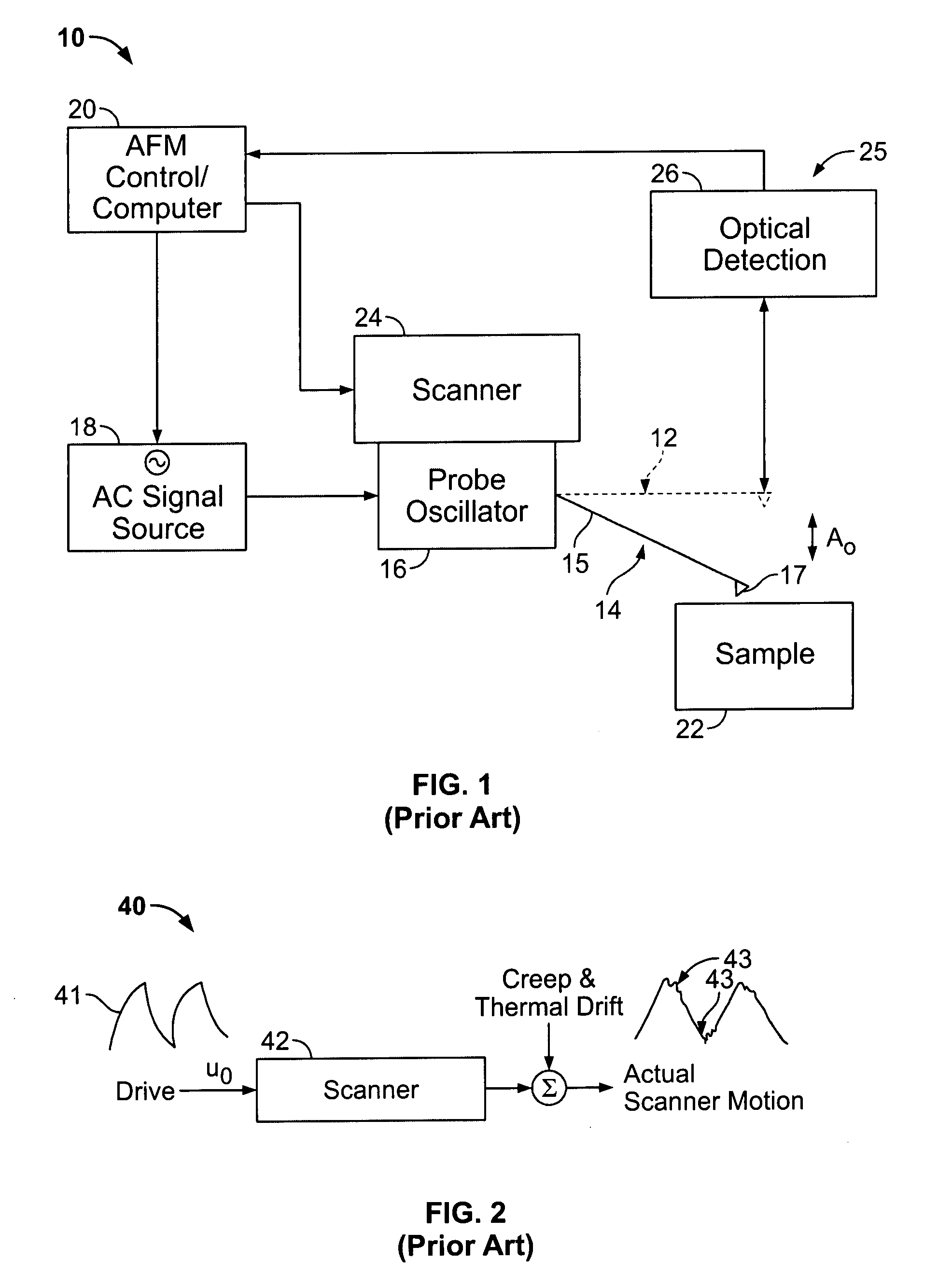
Moreover, drift,
hysteresis and
creep of the actuator operate to further compromise precisely positioning the probe and / or sample.
Hysteresis can therefore cause a large prior motion to compromise the response to a commanded move, even many minutes later.
After the command
voltage is applied, the piezo may move a desired distance, but continues to move uncontrollably due to the
creep effect.
Such effect can be more than 10% of the commanded motion, causing a substantial positioning error.
Notably, these issues exist whether the probe device of the AFM is coupled to the actuator (i.e., the case in which the probe device moves in three orthogonal directions), or the sample is coupled to the actuator.
Moreover, though known solutions attempt to overcome the above-noted challenges, they have been imperfect.
For example, some open loop methods of driving the SPM actuator have been implemented in an attempt to compensate for limitations of the controller and actuators, and thereby limit poor tracking between desired scanning movement and actual movement.
This technique has been successful for counteracting actuator non-linearities, but the calibration procedure is cumbersome and it does not adequately address drift and
creep.
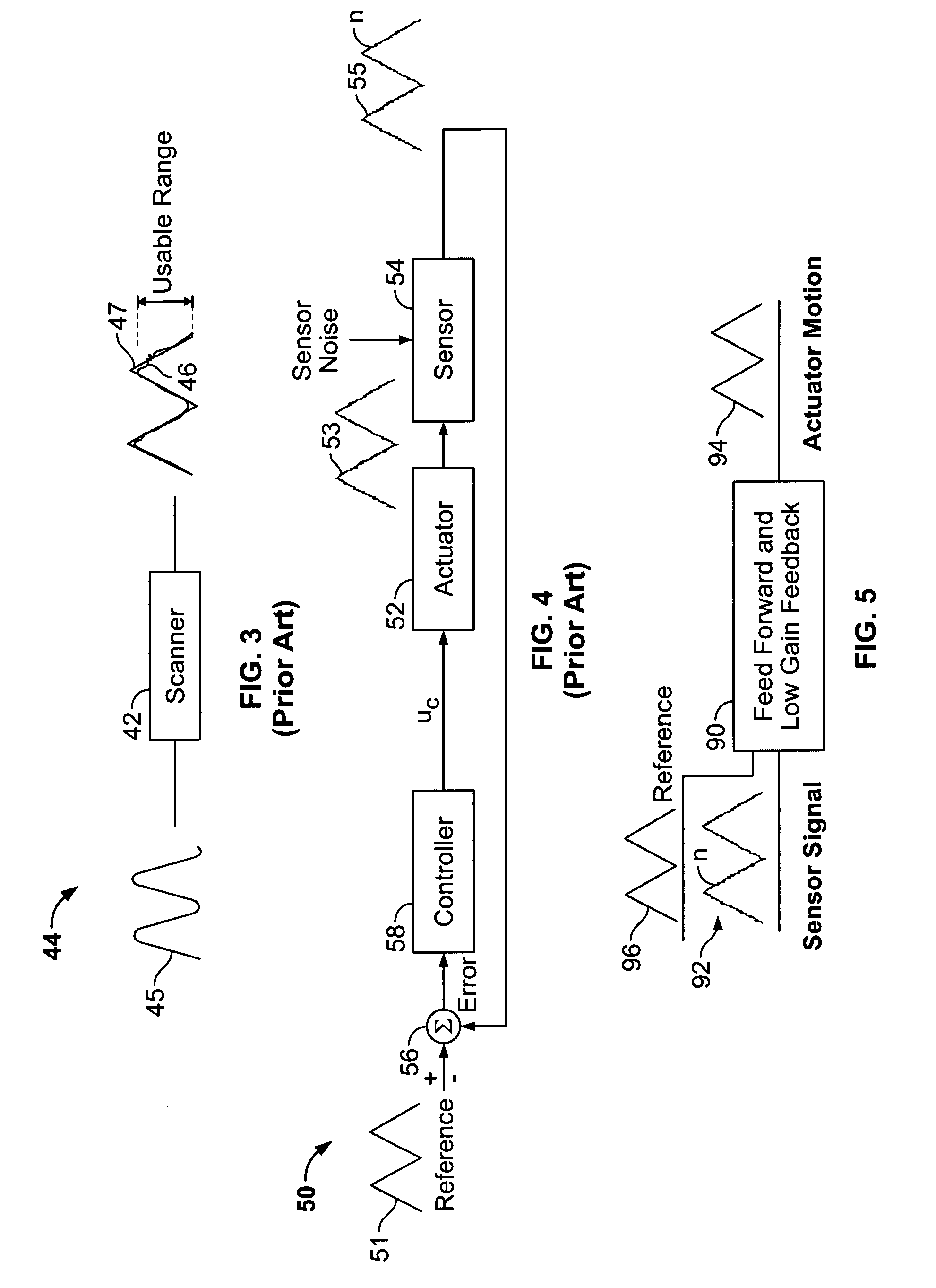
Moreover, due to the
rounding, the
usable range of the drive is limited.
Because such open loop solutions can be complicated and often still do not provide acceptable position accuracy, especially at higher scan speeds, some SPMs employ
closed loop position control.
However, the bandwidth of the
position control feedback is often limited (discussed below), and the noise introduced by the sensor employed to detect actual
scanner motion can degrade
image quality through the
feedback loop, thus further limiting the ability of the AFM to track a fast command
signal during scanning, and thus produce acceptable images, at greater speeds.
Due to the noise limitation, many
position control feedback systems are disabled at small scan sizes.
In sum, at higher imaging speeds, the performance of the position feedback
system often degrades SPM
system performance.
Although useful for minimizing the effects of system conditions that have an adverse
impact on the ability of the
scanner to track desired motion, the bandwidth of conventional control systems 50 is limited.
There are several reasons for the limits in conventional position control systems, including scanner resonances and
position sensor noise and bandwidth limitations.
The inability of SPM scanners to scan large areas at high speeds without unwanted oscillations is a major
bottleneck to operating SPMs at greater speeds.
Additionally, these resonances limit how fast the controller 58 can operate.
Even before the condition of
instability, underdamped resonances can cause oscillations and overshoot in the actual motion of the scanner.
As a result, operation of conventional position control feedback loops is limited to a small fraction of the scanner's lowest observed
resonance, or “fundamental resonant frequency.” Notably, the lowest observed
resonance is most often axis dependent, with
coupling of the response typically being present among axes, thereby limiting the lowest observed resonance of the scanner / actuator.
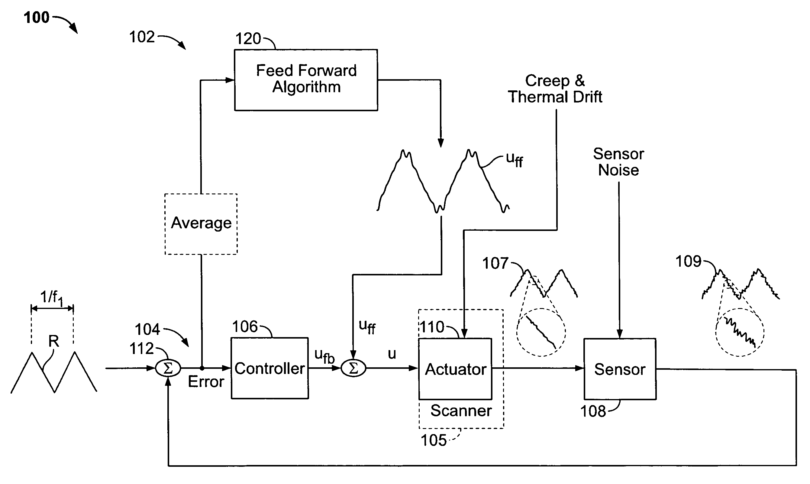
Moreover, sensor 54 introduces noise to the system that compromises the controller's ability to satisfactorily track the desired motion.
The resulting image is therefore correspondingly compromised by all the sensor noise that is within the feedback bandwidth.
The
control signal uc, though compensating for
system dynamics including thermal drift and creep, may not yield the desired scanner motion because of the additional
high frequency noise introduced via the sensing scheme.
Sensor noise is typically a function of bandwidth, so the position sensor
electronics and / or the controller may limit the bandwidth of the sampled position sensor
signal to reduce the image of this noise.
The effect of a limited sensor bandwidth, however, is typically the accumulation of phase shifts in the sensor output versus the actual motion of the scanner.
Destructive interference will occur between the results of the two impulses and quickly damp the unwanted oscillation.
That said, because such
closed loop schemes are intended to operate over a wide bandwidth, the problems associated with sensor noise continue to limit system performance.
An open loop
model based controller, while compensating for scanner resonances, will still be subject to unwanted motion within the system, including scanner nonlinearities, creep and thermal drift.
Thus, tracking in such systems remains imperfect.
Such models associated with
feed forward controllers are difficult to control and typically produce less than ideal results, primarily due to the challenge of creating a workable model that fits all desired imaging conditions.
Such imaging conditions often produce a change in the mechanical environment and therefore a change of the
transfer function used in the model.
Ultimately, producing linear scanner motion is very difficult to achieve with these open loop solutions.
This is most often a difficult task that typically yields an imperfect result, given the inability to accurately model or predict particular environmental conditions.
Moreover, due to this difficulty, such systems are not sufficiently robust for many applications.
The open loop
feed forward scheme can be effective in compensating the scanner non-
linearity if the calibration is accurate and remains constant throughout the usage, but it still does not address the resonance
distortion introduced by the impulse forces at the turning point of the linear triangular scanning.

