Electric Double-Layer Capacitor

a double-layer capacitor and capacitor technology, applied in the direction of capacitors, hybrid capacitor electrolytes, capacitor electrolytes, etc., can solve the problems of electric double-layer formation, propylene carbonate suffers from limitations in the application of propylene carbonate to large-sized products requiring high output and low resistance, and high inflammability

Active Publication Date: 2008-11-20
VINATECH CO LTD
View PDF9 Cites 19 Cited by
  • Summary
  • Abstract
  • Description
  • Claims
  • Application Information

AI Technical Summary

Problems solved by technology

In addition, at the interface between an electrode in the solid state and an aqueous electrolyte solution in the liquid-state, selective adsorption of either cations or anions in the solution or dissociation of solid surface molecules, arrangement / adsorption of dipoles toward the interface and the like may result in formation of electric double-layers.
However, propylene carbonate also suffers from limitations in application thereof to large-sized products requiring high output and low resistance, due to its own high resistivity.
Consequently, such propylene carbonate-based electrolytes pose problems associated with difficulty of application thereof to large-scale power supplies of hybrid vehicles or UPSs, requiring constant capacity under conditions of more than 100,000 cycle times.
In addition, acetonitrile is suitable for generating high output due to low viscosity and high solubility in salts, but exhibits various problems such as a low boiling point of 82° C., high inflammability and high probability of cyanide production upon occurrence of a fire.
Particularly when it is desired to design large-scale products using acetonitrile, application of heat higher than 140° C. results in sublimation of internal electrolytes which in turn causes the fatal problem of rapid explosion.
Further, acetonitrile is a member of organic cyanide compounds classified into categories of toxic substances, and therefore suffers from limitations in use thereof from a standpoint of technical design characteristics attaching great importance to environmental safety.

Method used


Image

  • Electric Double-Layer Capacitor
  • Electric Double-Layer Capacitor
  • Electric Double-Layer Capacitor

Examples


examples

[0056]Hereinafter, an electric double-layer capacitor in accordance with the present invention will be described in more detail with reference to the following examples. These examples are provided only for illustrating the present invention and should not be construed as limiting the scope and spirit of the present invention.

examples 1 through 11

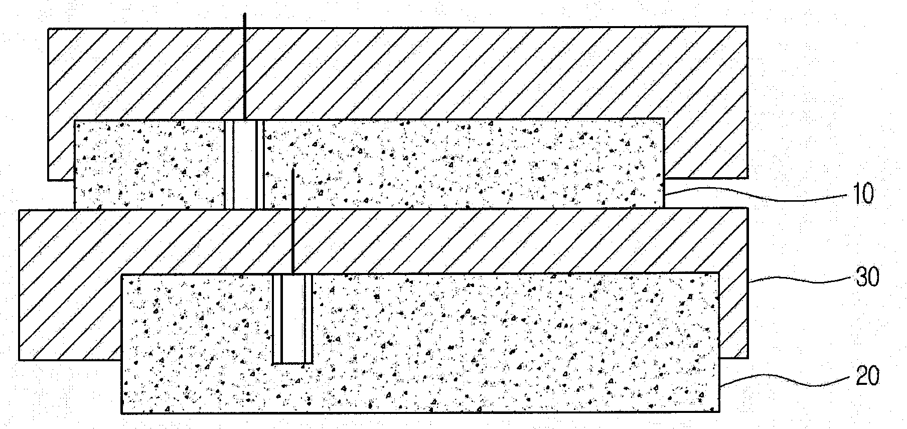
[0057]Using activated carbon (Kansai Cokes, MSP-20) having capacitance of 140 F / g, a specific surface area of 2200 m2 / g and a pore volume of 1.0 cc / g, as an electrode active material and using a slurry containing 80 wt % of activated carbon, 12 wt % of carbon black (Super-P), 3 wt % of carboxymethylcellulose (CMC), and 5 wt % of a polytetrafluoroethylene (PTFE) binder, thin films were coated with the same thickness on both sides of aluminum foil having a thickness of 20 μm, thereby fabricating electrodes having a thickness of 200 μm. The electrodes were cut into a size of 3 cm×40 cm, wound into a cylindrical form and then placed into metal cases having a size of D18 mm×L40 mm, thereby fabricating cells.

[0058]For Examples 1 through 11, total moles of electrolytes contained in the thus-fabricated cells were sequentially increased from 1M up to 2M, a mixed amount of tetraethylammonium tetrafluoroborate (TEABF4) and butylmethylpyrrolidinium tetrafluoroborate (BMPBF4) salts was adjusted,...

example 12

[0071]A cell was fabricated in the same manner as in Example 9, except that 1.5M ethylmethylpyrrolidinium tetrafluoroborate (EMPBF4) was used as a salt, instead of butylmethylpyrrolidinium tetrafluoroborate.


PUM


Abstract

Provided is an electric double-layer capacitor. The electric double-layer capacitor comprises an electrode portion composed of an anode and a cathode; a separator for providing electrical isolation between the anode and cathode; and an electrolyte solution which is filled in a space between the anode and cathode so as to form electric double-layers on surfaces of the anode and cathode upon application of a predetermined voltage, and in which a solvent and a solute are mixed so as to have a concentration of 1.25 to 2.5 mol/L.

Description

TECHNICAL FIELD[0001]The present invention relates to an electric double-layer capacitor. More specifically, the present invention relates to an electric double-layer capacitor utilizing an electrolyte containing an ionic liquid in order to maintain an electrolyte concentration at a constant level, and being capable of improving high-current discharge characteristics and cycle characteristics by adjusting the composition of a solvent.BACKGROUND ART[0002]In general, an electric double-layer is a structure wherein a thin film layer of an object exhibits continuous presence of positive charges at one side and continuous presence of negative charges at the other side, or distribution of positive and negative charges at the same surface density for two sides, and typically refers to a double layer composed of dipoles. Usually, rearrangement of charges and formation of an electric double-layer occur at the boundary between different materials.[0003]In addition, at the interface between an...

Claims


Application Information

Patent Timeline
Patent Type & Authority Applications(United States)
IPC IPC(8): H01G9/022H01G9/02
CPCH01G9/038H01G11/62Y02E60/13H01G11/60H01G9/022
Inventor SUNG, DO KYONGJUNG, JUN TAEHUR, JIN WOO
Owner VINATECH CO LTD
Why Eureka
Try Eureka