Layered carbon electrodes useful in electric double layer capacitors and capacitive deionization and methods of making the same

a carbon electrode and double layer technology, applied in the direction of electrolytic capacitors, coatings, chemistry apparatuses and processes, etc., can solve the problems of reducing reducing the efficiency of the electrode, so as to improve the mechanical integrity of the layered structure, and improve the effect of electronic resistan

Inactive Publication Date: 2008-12-04
CORNING INC
View PDF29 Cites 40 Cited by
  • Summary
  • Abstract
  • Description
  • Claims
  • Application Information

AI Technical Summary

Benefits of technology

[0022]Layered structures and carbon electrodes made according to the methods described herein possess one or more desirable advantages, for example, the electrically conductive support of the layered structure and the electrically conductive porous carbon support of the carbon electrode provide a high performance electrical backplane for the layered structure and the carbon electrode.
[0023]The carbonizable material which is within the electrically conductive support of the layered structure, or the carbonized material within the electrically conductive porous carbon support of the carbon electrode, can improve the mechanical integrity of the layered structure and the carbon electrode by toughening the otherwise brittle supports by forming a strong, interlocking, mechanical bond between the support and the carbon particles. The carbonized material provides both mechanical bonding and additional electrical connectivity between the carbon particles and the support in the carbon electrode.
[0024]Also, increased electrical contact between the carbon particles in the carbon cover layer and the support can be achieved and maintained in the carbonized, or carbonized and activated, carbon electrode, thus yielding a carbon electrode with low electronic resistance.
[0026]Further advantages of layered structures and carbon electrodes according to the present invention are that the layered structures and carbon electrodes and methods of making the carbon electrodes can utilize a range of different carbon powders in the carbon cover layer, providing an opportunity for performance enhancement and / or fine tuning. The mechanical properties, for example, strength and integrity of the layered structures and the carbon electrodes (relative to conventional CDI electrodes) enable the layered structures and the carbon electrodes of the present invention to easily be used in parallel, transverse, or hybrid parallel / transverse flow geometries. The methods of making the carbon electrodes and the inexpensive components result in carbon electrodes which can be increasingly cost-effective.

Problems solved by technology

The aerogel surface of these electrode sheets and the carbon paper itself are delicate and need to be protected from mechanical stressing which can cause damage to the electrodes, rendering the electrodes inoperable.
The resulting electrodes possess good CDI performance, but are extremely costly.
Limited success has been achieved at applying subcritical drying to reduce cost.
Also, these electrodes possess a very modest level of total capacitance per unit area, since the aerogel layer is thin and possesses limited surface area.
This reduced level of capacitance increases the number of electrode sheets required for a given system which further increases the cost.
However, the particle to particle connectivity of the carbon particles in the activated carbon is typically poor and these electrodes have high electronic resistance compared to the monolithic aerogel electrodes.
A separate current collector sheet, typically made of rolled exfoliated graphite material, is clamped to the electrode back surface with a large compressive force to obtain the necessary electrical performance, thus increasing the cost and the complexity of a CDI device made using these electrodes.
Also these rolled composite sheets, due to the purely mechanical nature of the PTFE / carbon bonding, have only modest erosion resistance.
The resulting electrodes have some disadvantages, for example, limited mechanical strength, since the electrodes comprise a porous and brittle material.
Thus, manufacturing thin, large diameter electrodes for high performance is challenging and packaging the electrodes into a CDI system is also challenging.
Also, because they do not have a conductive graphitic backplane, their electronic conductivity is low as compared to the carbon paper-based aerogel electrodes.

Method used


Image

  • Layered carbon electrodes useful in electric double layer capacitors and capacitive deionization and methods of making the same
  • Layered carbon electrodes useful in electric double layer capacitors and capacitive deionization and methods of making the same
  • Layered carbon electrodes useful in electric double layer capacitors and capacitive deionization and methods of making the same

Examples


Embodiment Construction

[0041]Reference will now be made in detail to various embodiments of the invention, examples of which are illustrated in the accompanying drawings. Wherever possible, the same reference numbers will be used throughout the drawings to refer to the same or like parts.

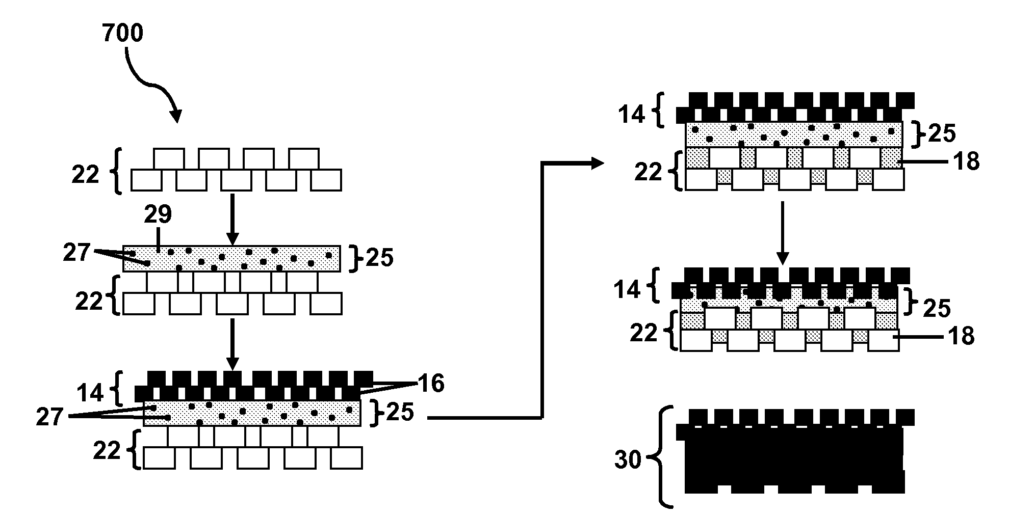
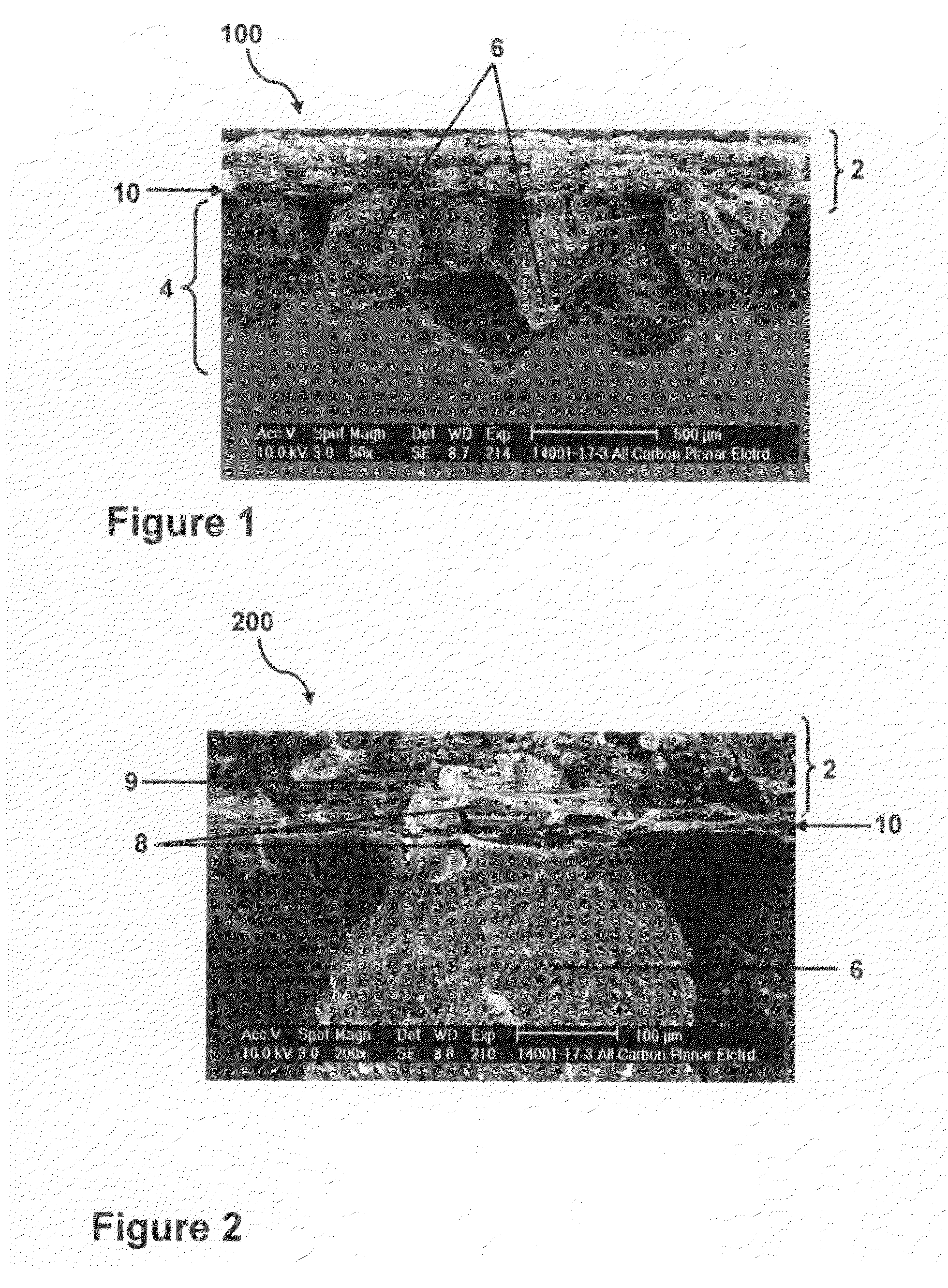
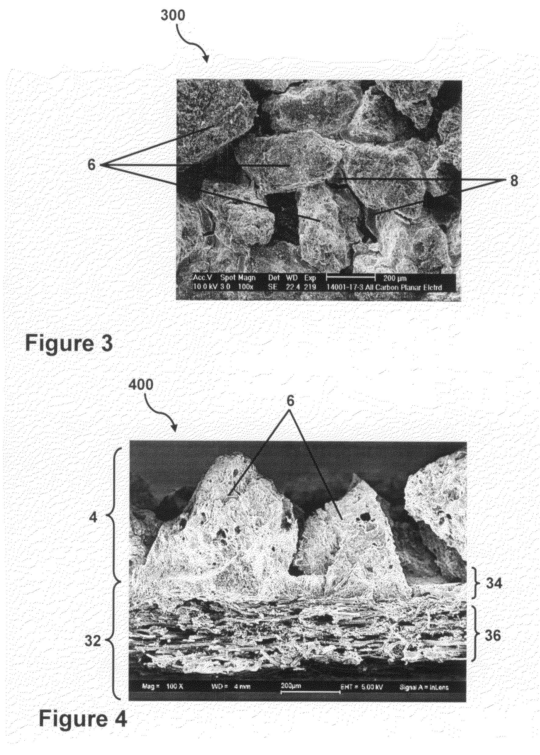
[0042]In embodiments, as shown in FIG. 1, FIG. 2 and FIG. 3, a carbon electrode 100, 200, 300 respectively comprises a carbon cover layer 4 comprising carbon particles 6 in contact with an electrically conductive porous carbon support 2. A carbonized material 8 is within the electrically conductive porous carbon support 2 and provides a bond to the carbon particles 6 at the interface 10 with the carbon cover layer 4.

[0043]In another embodiment, as shown in FIG. 5, a layered structure is disclosed. The layered structure 500 comprises an electrically conductive support 52, an adjacent carbon cover layer 54 comprising carbon particles or precursors thereof 56 in contact with the electrically conductive support 52 and a carbo...


PUM

PropertyMeasurementUnit
thicknessaaaaaaaaaa
thicknessaaaaaaaaaa
diameteraaaaaaaaaa

Abstract

Carbon electrodes for use in, for example, Capacitive Deionization (CDI) of a fluid stream or, for example, an electric double layer capacitor (EDCL). Methods of making the carbon electrodes are also described. The carbon electrode comprises an electrically conductive porous carbon support and a carbon cover layer comprising carbon particles in contact with the electrically conductive porous carbon support. A carbonizable material is within the electrically conductive porous carbon support and provides a bond to the carbon particles at the interface of the electrically conductive porous carbon support and the carbon cover layer. The electrically conductive porous support in some embodiments is a layered structure, where one of the layers is a carbonizable paste layer having electrically conductive particles mixed therein.

Description

BACKGROUND[0001]1. Field of the Invention[0002]The present invention relates generally to carbon electrodes and layered structures and more particularly to an all carbon electrode and a layered structure useful for electric double layer capacitors and / or for capacitive deionization and methods of making the same.[0003]2. Technical Background[0004]An electric double layer capacitor (EDLC) is an example of a capacitor that typically contains carbon electrodes (separated via a porous separator), current collectors and an electrolyte solution. When electric potential is applied to an EDLC cell, ionic current flows due to the attraction of anions to the positive electrode and cations to the negative electrode. Electric charge is stored at the interface between each polarized electrode and the electrolyte solution.[0005]EDLC designs vary depending on application and can include, for example, standard jelly roll designs, prismatic designs, honeycomb designs, hybrid designs or other designs...

Claims


Application Information

Patent Timeline
Patent Type & Authority Applications(United States)
IPC IPC(8): H01G9/042B05D5/12
CPCC02F1/46109C02F1/4691C02F2001/46133C02F2001/46138Y10T29/417H01G11/42Y02E60/13H01G11/32C02F2001/46161
Inventor BOURCIER, ROY JOSEPHST CLAIR, TODD P.MAZUMDER, PRANTIKNADJADI, JR., ANDREW R.SCHNEIDER, VITOR MARINO
Owner CORNING INC
Why Eureka
Try Eureka