Carbonaceous solid fuel gasifier utilizing dielectric barrier non-thermal plasma

a solid fuel gasifier and dielectric barrier technology, applied in gaseous fuels, gas-gas reaction processes, combustible gas production, etc., can solve the problems of high temperature, degrade the costly conventional catalysts required for practical implementation, and the environment is hostile, so as to reduce the activation energy barrier. , the effect of reducing the activation energy barrier

Inactive Publication Date: 2008-12-25
RGT UNIV OF CALIFORNIA
View PDF9 Cites 23 Cited by
  • Summary
  • Abstract
  • Description
  • Claims
  • Application Information

AI Technical Summary

Benefits of technology

[0035]An advantage of the present invention is its lower operating conditions. For example, the conventional operating conditions required to overcome the activation energy barrier (e.g., about 50-80 kilocalories (“kcal”) / mole) for hydrogasification of coal (C+2H2→CH4) (i.e., the process stream comprises hydrogen and the fuel gas comprises methane) are a temperature around 1000° C. and a pressure around 60 atmospheres or higher. The present invention, however, uses the non-thermal plasma to produce hydrogen atoms, which reduce the activation energy barrier. Because the activation energy barrier is lower, the temperature and pressure necessary to overcome the activation energy barrier are also lower.
[0036]By considering the above parameters, the present invention also includes a process for producing a fuel gas from a carbon-containing material comprising generating a non-thermal plasma, and contacting the carbon-containing material with the non-thermal plasma for a time and temperature sufficient to form the fuel gas.
[0037]The present invention is more particularly described in the following example that is intended as illustrative only because numerous modifications and variations will be apparent to those skilled in the art.

Problems solved by technology

A conventional gasification process, however, typically involves a hostile environment that includes high temperatures, possibly high pressures, abrasion, and poisoning of catalysts by sulfur or other contaminants in the solid fuel.
Moreover, such severe operating conditions rapidly degrade the costly conventional catalysts required for practical implementation of gasification.

Method used


Image

  • Carbonaceous solid fuel gasifier utilizing dielectric barrier non-thermal plasma
  • Carbonaceous solid fuel gasifier utilizing dielectric barrier non-thermal plasma
  • Carbonaceous solid fuel gasifier utilizing dielectric barrier non-thermal plasma

Examples


example 1

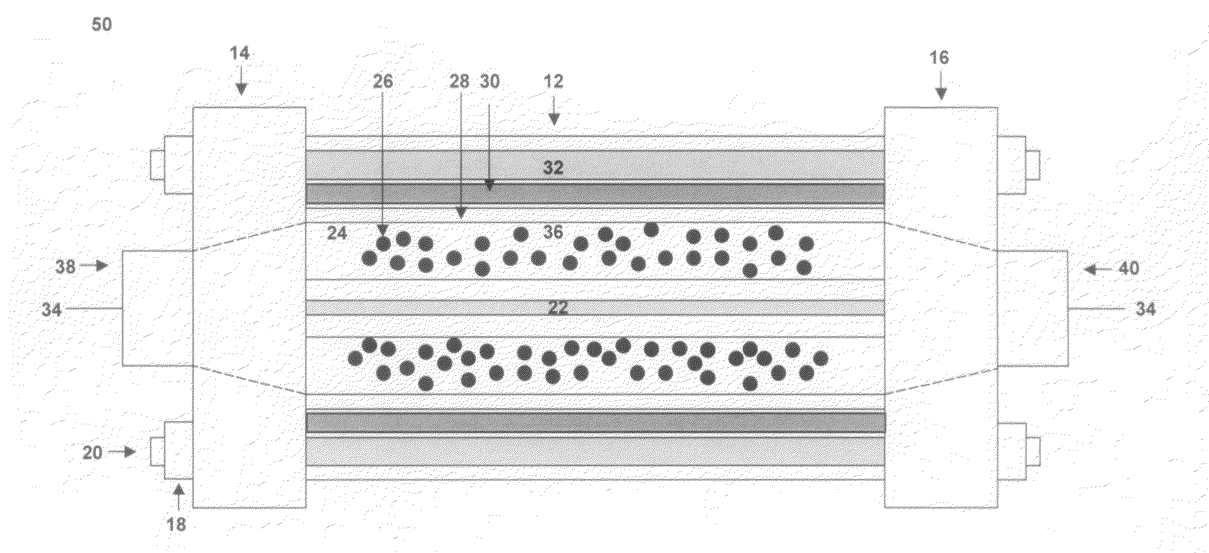
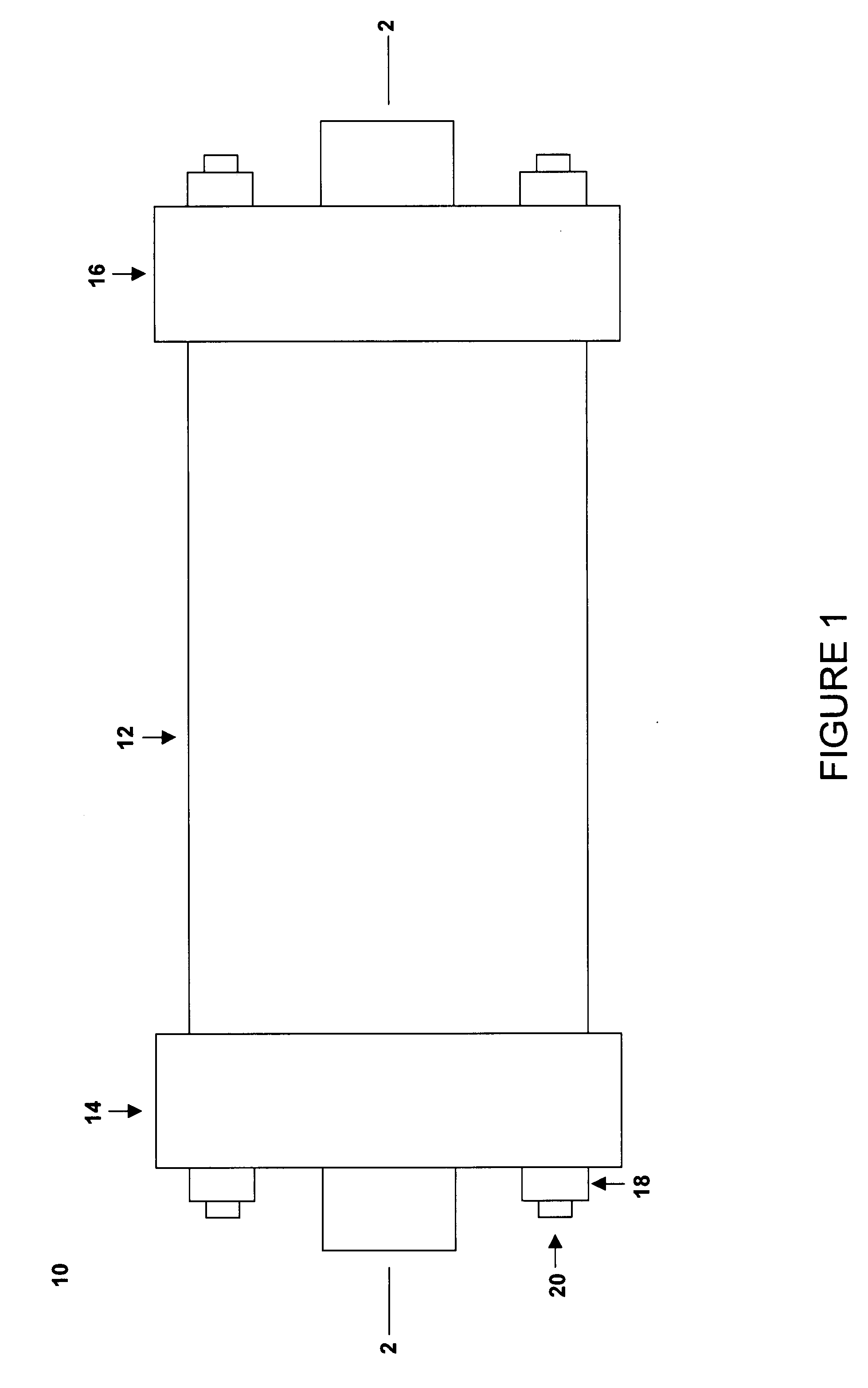
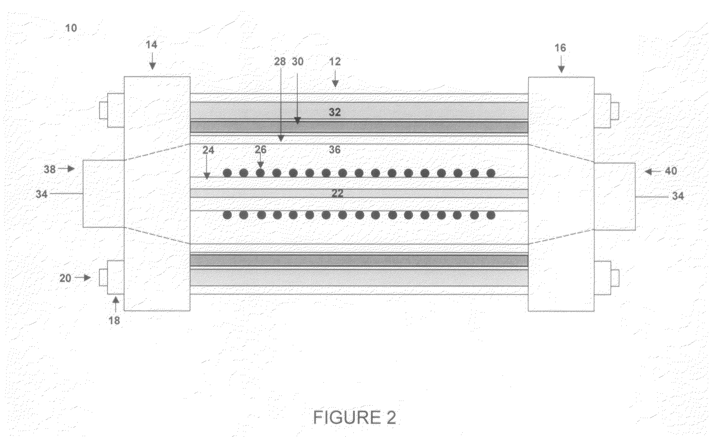
[0038]EXAMPLE 1 is an embodiment of the invention that was similar to the system shown in FIGS. 1 and 2. The system comprised a coaxial-cylinder dielectric barrier discharge reactor and associated carbon gasifier. The high voltage electrode was a 52 centimeter (“cm”) long stainless steel wire that was inserted into a 50 cm long alumina (e.g., Al2O3) ceramic tube with a 0.5 cm outside diameter (“OD”). The grounded electrode was a 30 cm long copper mesh electrode that was placed outside a 45 cm long quartz tube with a 1.68 cm OD. A high voltage alternating current transformer (Eurocom Model 92-0152-70) operating at a frequency of about 450 Hz powered the high voltage stainless steel electrode. The carbon-containing material was an activated carbon powder with a 250 μm mean diameter. One hundred milligrams of the carbon-containing material were placed on the surface of the ceramic tube. The single-pass process stream was 99.99% by volume hydrogen gas flowing at 0.5 liters / minute (“L / mi...


PUM

PropertyMeasurementUnit
temperatureaaaaaaaaaa
sizeaaaaaaaaaa
sizesaaaaaaaaaa

Abstract

A system for producing a fuel gas from a carbon-containing material is provided that includes a non-thermal plasma generator, an electric power source, a process stream inlet, and a product stream outlet. The non-thermal plasma generator includes a high voltage electrode separated from a grounded electrode by a modification passage. Moreover, a dielectric layer exists between the high voltage electrode and the grounded electrode. The electric power source is energizable to create non-thermal electrical microdischarges within the modification passage. As the process gas flows through the system, the carbon-containing material is converted to fuel gas.

Description

RELATED APPLICATIONS[0001]This application claims the benefit of U.S. Provisional Application No. 60 / 936,961, filed Jun. 21, 2007.STATEMENT OF FEDERAL RIGHTS[0002]The United States government has rights in this invention pursuant to Contract No. DE-AC52-06NA25396 between the United States Department of Energy and Los Alamos National Security, LLC for the operation of Los Alamos National Laboratory.FIELD OF INVENTION[0003]The present invention pertains generally to a system and process for producing a fuel gas from a carbon-containing material, and more particularly to non-thermal plasma reactors.BACKGROUND[0004]Gasification of carbonaceous solid fuels, such as coal and biomass, has become of increasing interest and importance because of rapidly rising petroleum prices, dwindling domestic petroleum and natural gas resources, and the increased dependency by the United States on foreign petroleum imports. Gasification of coal and biomass has been widely practiced for over 100 years, an...

Claims


Application Information

Patent Timeline
Patent Type & Authority Applications(United States)
IPC IPC(8): C01B3/02C07C2/00B01J19/08
CPCC10J3/00C10J3/466C10J2300/0966C10J2300/1238H05H2245/1215H05H1/2406H05H2001/2431H05H2001/2443H05H2240/20C10L3/08H05H1/2443H05H1/2431H05H2245/17
Inventor KIM, YONG HOROSOCHA, LOUIS A.ANDERSON, GRAYDON K.ZIOCK, HANS-JOACHIMABBATE, SARASANCHEZ-GONZALEZ, RODRIGO
Owner RGT UNIV OF CALIFORNIA
Why Eureka
Try Eureka