Light emitting element, light emitting device, and electronic device

Inactive Publication Date: 2009-01-29
SEMICON ENERGY LAB CO LTD
View PDF44 Cites 56 Cited by
  • Summary
  • Abstract
  • Description
  • Claims
  • Application Information

AI Technical Summary

Benefits of technology

[0014]By an implementation of the present invention, a light emitting element, in which an operation failure due to crystallization of a compound included in a layer provided between a pair of electrodes is reduced, can be obtained. This is because, by mixing an aromatic hydrocarbon and a metal oxide, crystallization of each of the aromatic hydrocarbon and the metal oxide is disturbed by each other, and accordingly, a layer which is not easily crystallized can be formed.
[0015]By an implementation of the present invention, a light emitting element, in which a length of a light path through which emitted light passes can be easily changed, can be obtained. This is because a light emitting element in which a drive voltage increases very little, which depends on increase in a thickness of a mixed layer, can be obtained by providing the mixed layer including aromatic hydrocarbon and metal oxide between the electrodes, and accordingly, a distance between a light emitting layer and the electrode can be adjusted easily.
[0016]By an implementation of the present inv

Problems solved by technology

It is conceivable that the technique mentioned in Patent Document 1 is also effective; however, molybdenum oxide is easily crystallized, and accordingly, there is a problem that an operation failure of a light emitting element due t

Method used


Image

  • Light emitting element, light emitting device, and electronic device
  • Light emitting element, light emitting device, and electronic device
  • Light emitting element, light emitting device, and electronic device

Examples


embodiment mode 1

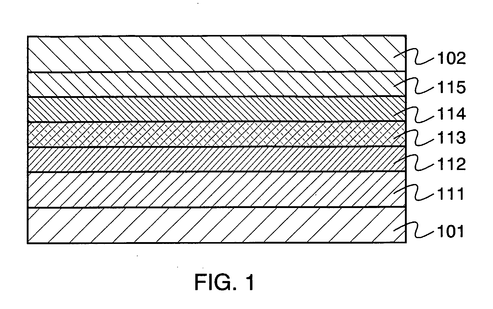
[0040]One mode of a light emitting element of the present invention will be explained with reference to FIG. 1.

[0041]FIG. 1 shows a light emitting element having a light emitting layer 113 between a first electrode 101 and a second electrode 102. In the light emitting element shown in FIG. 1, a mixed layer 111 is provided between the light emitting layer 113 and the first electrode 101. A hole transporting layer 112 is provided between the light emitting layer 113 and the mixed layer 111, and an electron transporting layer 114 and an electron injecting layer 115 are provided between the light emitting layer 113 and the second electrode 102. In such a light emitting element, when a voltage is applied to the first electrode 101 and the second electrode 102 so that the electric potential of the first electrode 101 gets higher than that of the second electrode 102, holes are injected in the light emitting layer 113 from the first electrode 101 side and electrons are injected in the ligh...

embodiment mode 2

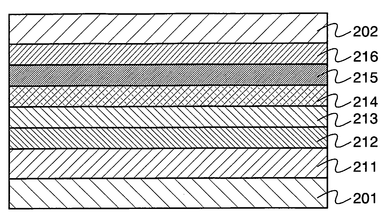
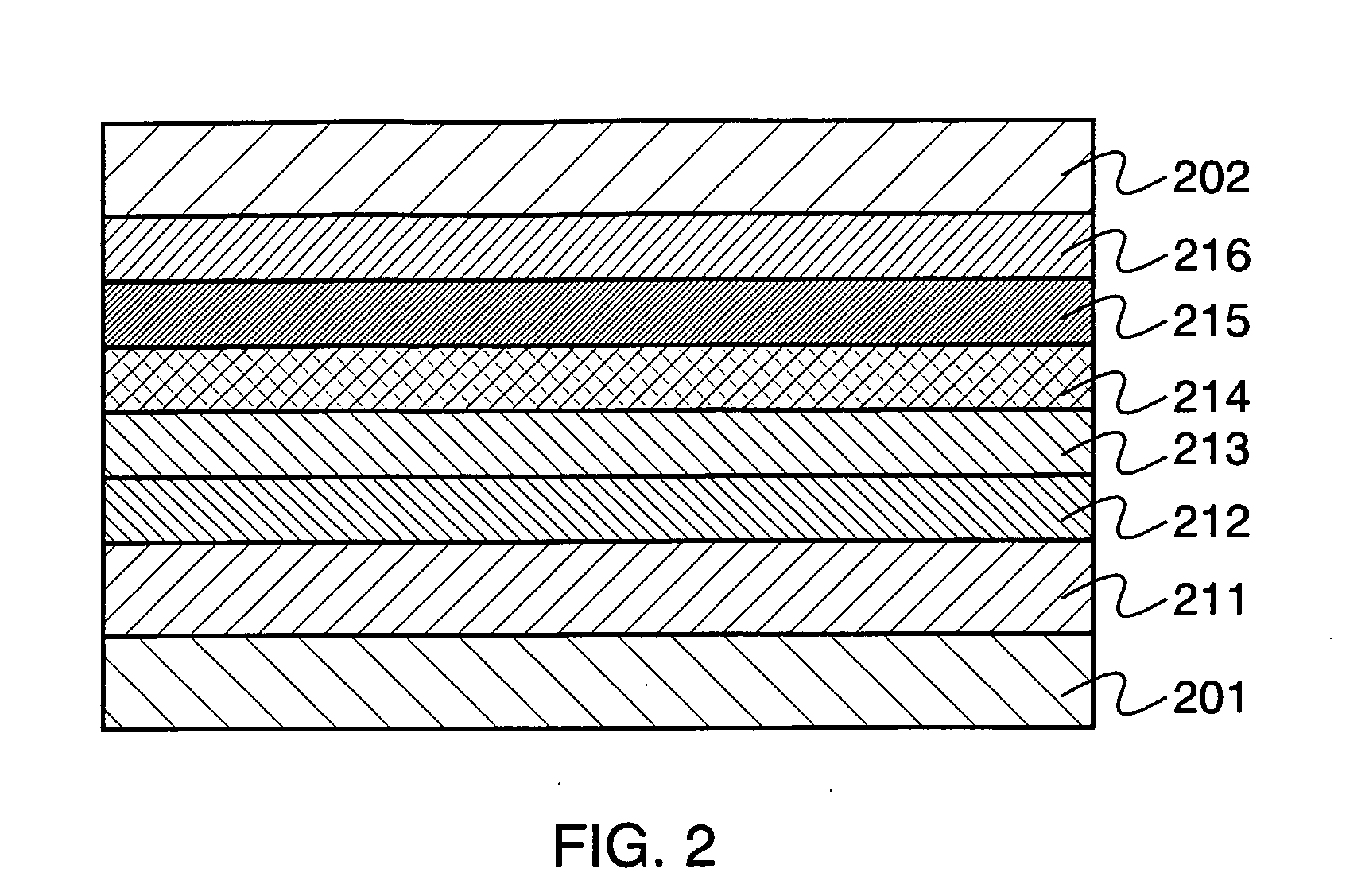
[0059]One mode of a light emitting element of the present invention will be explained with reference to FIG. 2.

[0060]FIG. 2 shows a light emitting element having a light emitting layer 213, a first mixed layer 215, and a second mixed layer 216 between a first electrode 201 and a second electrode 202, in which the light emitting layer 213 is provided closer to the first electrode 201 than the first mixed layer 215, and the second mixed layer 216 is provided closer to the second electrode 202 than the first mixed layer 215. In this light emitting element, a hole injecting layer 211 and a hole transporting layer 212 are provided between the light emitting layer and the first electrode 201, and an electron transporting layer 214 is provided between the light emitting layer 213 and the first mixed layer 215. The first mixed layer 215 is a layer including an electron transporting substance and a substance selected from alkali metal, alkaline earth metal, alkali metal oxide, alkaline earth...

embodiment mode 3

[0076]One mode of a light emitting element of the present invention will be explained with reference to FIG. 20. FIG. 20 shows a light emitting element having a plurality of light emitting layers, specifically, a first light emitting layer 413a, a second light emitting layer 413b, and a third light emitting layer 413c between a first electrode 401 and a second electrode 402. This light emitting element has a first mixed layer 421a and a second mixed layer 422a between the first light emitting layer 413a and the second light emitting layer 413b, and a first mixed layer 421b and a second mixed layer 422b between the second light emitting layer 413b and the third light emitting layer 413c. The first mixed layers 421a and 421b are layers including an electron transporting substance and a substance selected from alkali metal, alkali earth metal, alkali metal oxide, alkaline earth metal oxide, alkali metal fluoride, and alkaline earth metal fluoride. The second mixed layers 422a and 422b ...


PUM


Abstract

One aspect of the present invention is a light emitting element having a layer including an aromatic hydrocarbon and a metal oxide between a pair of electrodes. The kind of aromatic hydrocarbon is not particularly limited; however, an aromatic hydrocarbon having hole mobility of 1×10⁻⁶ cm2/Vs or more is preferable. As such aromatic hydrocarbon, for example, 2-tert-butyl-9,10-di(2-naphthyl)anthracene, anthracene, 9,10-diphenylanthracene, tetracene, rubrene, perylene, 2,5,8,11-tetra(tert-butyl)perylene, and the like are given. As the metal oxide, a metal which shows an electron-accepting property to the aromatic hydrocarbon is preferable. As such metal oxide, for example, molybdenum oxide, vanadium oxide, ruthenium oxide, rhenium oxide, and the like are given.

Description

TECHNICAL FIELD[0001]The present invention relates to a light emitting element having a layer including a light emitting substance between electrodes, a light emitting device having the light emitting element, and an electronic device.BACKGROUND ART[0002]A light emitting element, which has attracted attentions in recent years as a pixel of a display device or a light source of a lighting device, has a light emitting layer between electrodes, and a light emitting substance included in the light emitting layer emits light when a current flows between the electrodes.[0003]In the development area of such a light emitting element, it is one of the important objects to extend the lifetime of a light emitting element. This is because a light emitting element provided for a light emitting device is necessary to be operated favorably for a long period of time in order to use a light emitting device such as a lighting device or a display device for a long period of time in a favorable conditi...

Claims


Application Information

Patent Timeline
IPC IPC(8): H01J63/04
CPCH01L51/5048H10K50/14H10K85/615
Inventor IWAKI, YUJISEO, SATOSHIKAWAKAMI, TAKAHIROIKEDA, HISAOSAKATA, JUNICHIRO
Owner SEMICON ENERGY LAB CO LTD
Why Eureka
Try Eureka