Process for Denitration of Exhaust Gas

a technology of denitration and exhaust gas, which is applied in the direction of separation processes, arsenic compounds, silicon compounds, etc., can solve the problems of increasing treatment costs, difficult application of non-catalytic denitration, and significant obstacles in the process of removing harmful substances, so as to improve the reactivity of nitrogen oxides, reduce the reductive decomposition of nitrogen oxides in the denitration step, and achieve the effect of efficient formation of amine radicals

Inactive Publication Date: 2009-02-26
MITSUI E&S MACHINERY CO LTD
View PDF4 Cites 5 Cited by
  • Summary
  • Abstract
  • Description
  • Claims
  • Application Information

AI Technical Summary

Benefits of technology

[0018]As a result of the denitration process of the present invention, a portion of the nitrogen monoxide in exhaust gas is oxidized to form nitrogen dioxide, thereby raising the reactivity of the nitrogen oxides. For this reason, reductive decomposition of nitrogen oxides in the denitration step is made easier. Moreover, adding a nitrogen compound and a hydrocarbon compound to the high-temperature zone in the radical formation step allows for efficient formation of amine radicals due to the reactions between the hydroxy radicals formed from the hydrocarbon compound and the nitrogen compound. The amount of residual, unreacted nitrogen compound at this point is also low. Furthermore, by mixing these amine radicals with the pretreated gas containing nitrogen monoxide and nitrogen dioxide discharged from the preliminary step, nitrogen oxides can be efficiently decomposed by reduction in the denitration step.

Problems solved by technology

Similarly, the removal of harmful substances contained in the exhaust gas of engines such as diesel engines for ships and power generators, boiler exhaust gas, and plant off-gas is an important problem.
For this reason, the exhaust gas of the latter contains a large amount of sulfur oxides, and processing the gas to remove harmful substances is a significant obstacle.
50° C. to 450° C.) exhaust gas exhausted from diesel engines such as those on ships and power generators, it is necessary to pre-treat the exhaust gas to heat it and raise the temperature thereof, which in turn leads to increased treatment costs and makes the application of non-catalytic denitration problematic.
In addition, while non-catalytic denitration using ammonia achieves a high denitration rate at the laboratory level, it has been difficult to obtain a denitration rate exceeding 50% in an actual furnace such as a boiler.
However, the denitration rate of this process is only approximately 40% under equimolar conditions of nitrogen oxides and ammonia.
Furthermore, if ammonia is excessively supplied in order to raise the denitration rate, unreacted ammonia remains and treatment costs increase.
Moreover, in th

Method used


Image

  • Process for Denitration of Exhaust Gas
  • Process for Denitration of Exhaust Gas
  • Process for Denitration of Exhaust Gas

Examples


embodiment 1

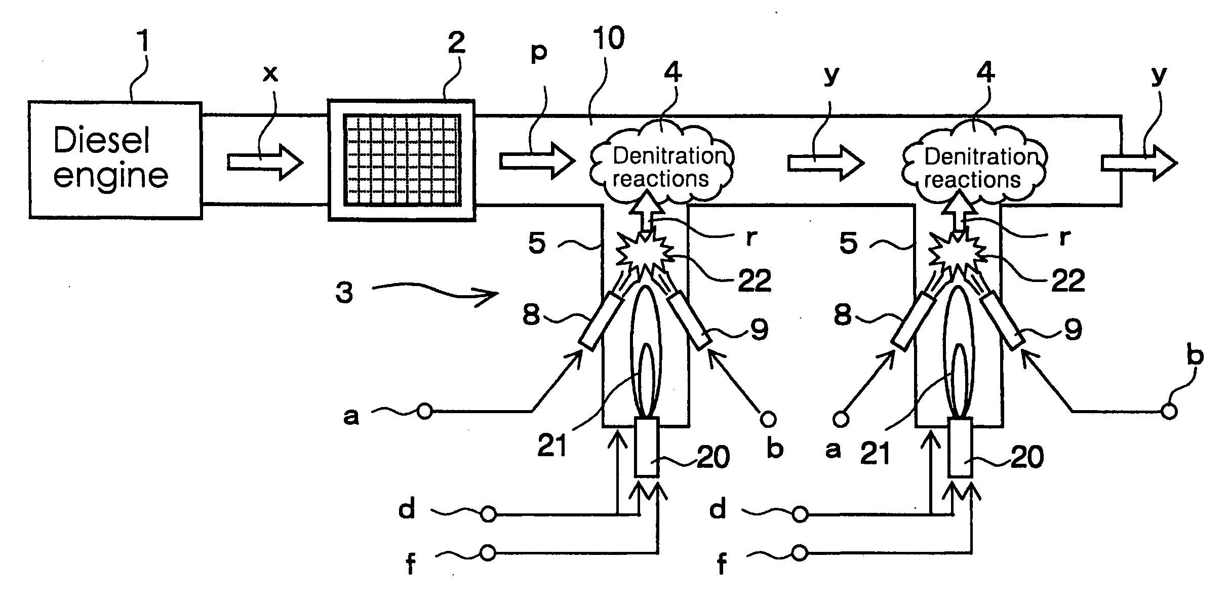
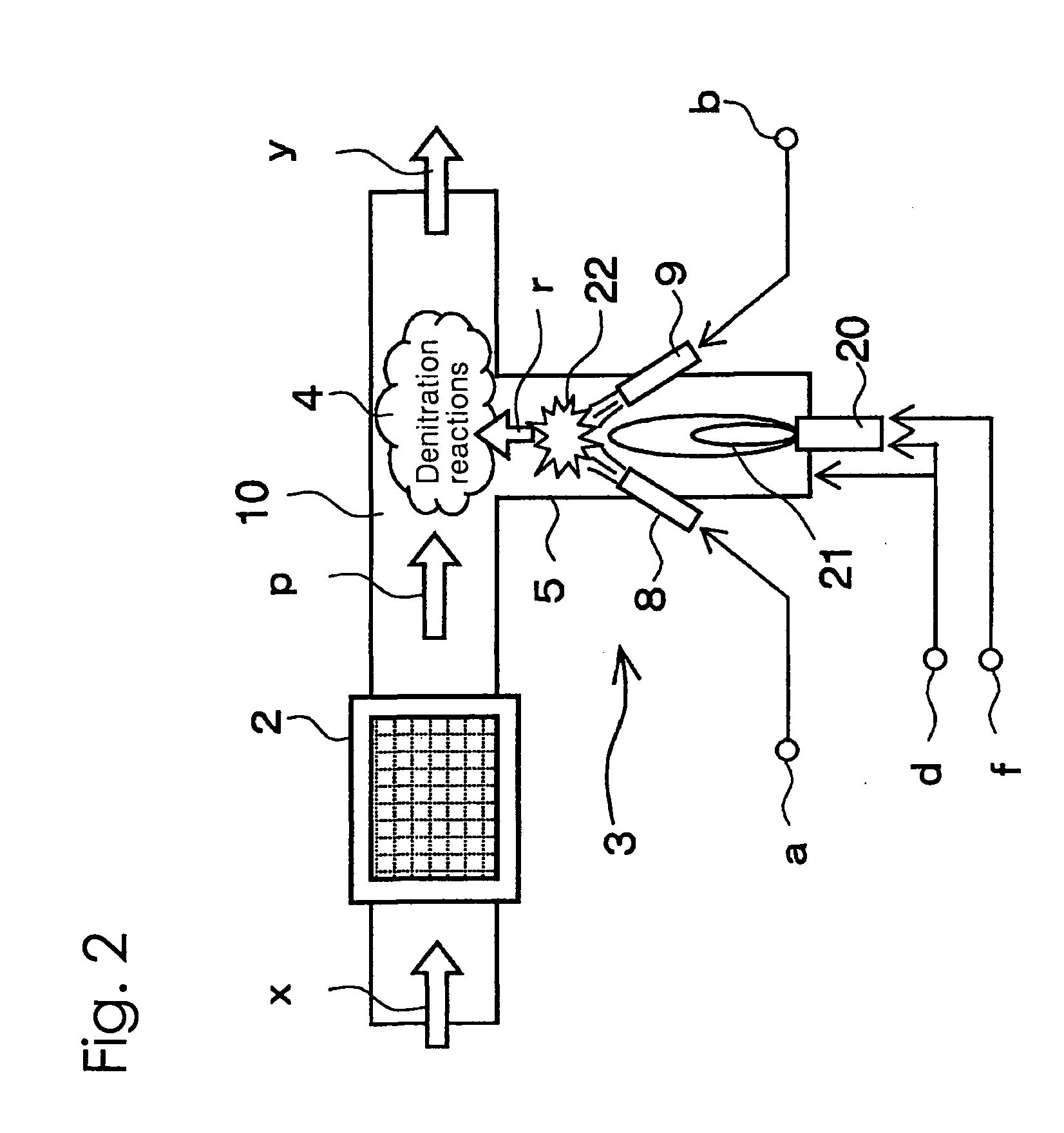
[0074]The angles formed by the center lines of the nozzle 8 and the nozzle 9 of the radical formation step 3 with the center line of the pipe portion 5 were both set to 45 degrees, and the points of intersection of the center lines of the nozzle 8 and the nozzle 9 with the center line of the pipe portion 5 were both set up so as to be positioned at a distance of 10 cm from the inner wall surface of the flue 10. In addition, the position of the burner and the strength of the flame were adjusted so as to bring the temperature of the area near the above intersection points to be 800° C. to 900° C.

[0075]A pulsed plasma generator was used as the means for the oxidation process of the preliminary step, and the denitration process was conducted so as not to activate the second denitration step. Furthermore, the exhaust gas temperature was made to be 300° C. at the measuring point 52a. Ammonia was used for the nitrogen compound blown from the nozzle 8, and propane gas was used for the hydro...

embodiment 2

[0080]The angles formed by the center lines of the nozzle 8 and the nozzle 9 of the radical formation step 3 with the center line of the pipe portion 5 were both set to 45 degrees, and the points of intersection of the center lines of the nozzle 8 and the nozzle 9 with the center line of the pipe portion 5 were both modified in the setup so as to be positioned at a distance of 5 cm from the inner wall surface of the flue 10. In addition, the position of the burner and the strenth of the flame were adjusted so as to bring the temperature of the area near the above intersection points to be 800° C. to 900° C.

[0081]The exhaust gas temperature at the measuring point 52a was made to be 250° C., NOx concentration and SO2 concentration was modified to the values shown in Table 3, and denitration treatment was conducted using a pulsed plasma generator in the preliminary step followed by a first and a second denitration step. Ammonia was used for the nitrogen compound blown from the nozzle 8...


PUM

PropertyMeasurementUnit
Temperatureaaaaaaaaaa
Fractionaaaaaaaaaa

Abstract

A denitration process for removing nitrogen oxides contained in low-temperature exhaust gas at a high denitration rate; namely, a denitration process for reductively removing nitrogen oxides contained in an exhaust gas (x) containing nitrogen monoxide and sulfur dioxide. The process comprises a preliminary step 2 of partially oxidizing nitrogen monoxide in the exhaust gas to form nitrogen dioxide, a radical formation step 3 of adding a nitrogen compound and a hydrocarbon compound to a high-temperature zone 22 to form amine radicals (r), and a denitration step 4 of mixing the amine radicals (r) with the pretreated gas (p) containing nitrogen monoxide and nitrogen dioxide that was discharged from the preliminary step 2. As a result, nitrogen oxides in the exhaust gas (x) are reductively decomposed.

Description

TECHNICAL FIELD[0001]The present invention relates to a process for the denitration of exhaust gas, and more specifically, to a process for the denitration of exhaust gas wherein nitrogen oxides are reductively removed from exhaust gas exhausted from an engine such as a diesel engine for a ship or power generator.BACKGROUND ART[0002]In recent years, much attention has been focused on the reduction of particulate matter and nitrogen oxides exhausted from automotive diesel engines such as those on buses and trucks. Similarly, the removal of harmful substances contained in the exhaust gas of engines such as diesel engines for ships and power generators, boiler exhaust gas, and plant off-gas is an important problem. However, while automotive diesel engines use diesel fuel oil for fuel, which has a low sulfur content, diesel engines such as those on ships and power generators use high sulfur content fuel known as Class A or Class C fuel oils (JIS standard). For this reason, the exhaust g...

Claims


Application Information

Patent Timeline
IPC IPC(8): B01D53/56
CPCB01D53/60F01N2610/10B01D2251/20B01D2257/302B01D2257/404F01N3/103F01N3/106F01N3/206F01N3/36F01N2240/14F01N2240/16F01N2240/28F01N2240/30F01N2470/04F01N2510/06F01N2510/067F01N2570/14F01N2610/02F01N2610/03B01D53/9409Y02A50/20B01D53/56B01D53/74F01N3/08F01N3/24
Inventor KANDA, NOBUYASUSUGIURA, KIMIHIKOIBARAGI, SHOICHITAKAHASHI, YOUICHITSUKUI, YUTAKA
Owner MITSUI E&S MACHINERY CO LTD
Why Eureka
Try Eureka